Waste gas treatment equipment for garbage treatment equipment

A technology of waste gas treatment equipment and garbage treatment equipment, which is applied in the direction of climate change adaptation, use of liquid separation agent, separation method, etc., can solve problems such as easy accumulation of impurities, poor waste gas treatment efficiency and effect, and pipeline blockage, and reduce the use of Low cost, simple and convenient maintenance, and the effect of avoiding clogging

Pending Publication Date: 2022-08-09
苏州傲龙环保科技有限公司
View PDF0 Cites 0 Cited by
  • Summary
  • Abstract
  • Description
  • Claims
  • Application Information

AI Technical Summary

Problems solved by technology

[0002] With the strengthening of people's awareness of environmental protection, more and more waste disposal equipment has been put into people's daily life support, through which waste disposal equipment can turn kitchen waste and other waste into fertilizer and other materials, which can be recycled; and waste disposal equipment is processing Exhaust gas will be generated in the process of garbage disposal. At present, most of the treatment methods are to discharge the exhaust gas directly into the air; but this will pollute the air and cause discomfort to the surrounding staff.
[0003] In order to solve this problem, some waste treatment equipment on the market is currently equipped with waste gas treatment mechanisms to achieve waste gas purification by spraying, but its structural design is not reasonable enough, resulting in poor efficiency and effect of waste gas treatment; and It is difficult to clean the exhaust gas pipeline in the machine. After a long time of use, it is easy to accumulate impurities and even cause pipeline blockage

Method used


Image

  • Waste gas treatment equipment for garbage treatment equipment
  • Waste gas treatment equipment for garbage treatment equipment
  • Waste gas treatment equipment for garbage treatment equipment

Examples


Embodiment Construction

[0015] The present invention will be further described in detail below with reference to the accompanying drawings and specific embodiments.

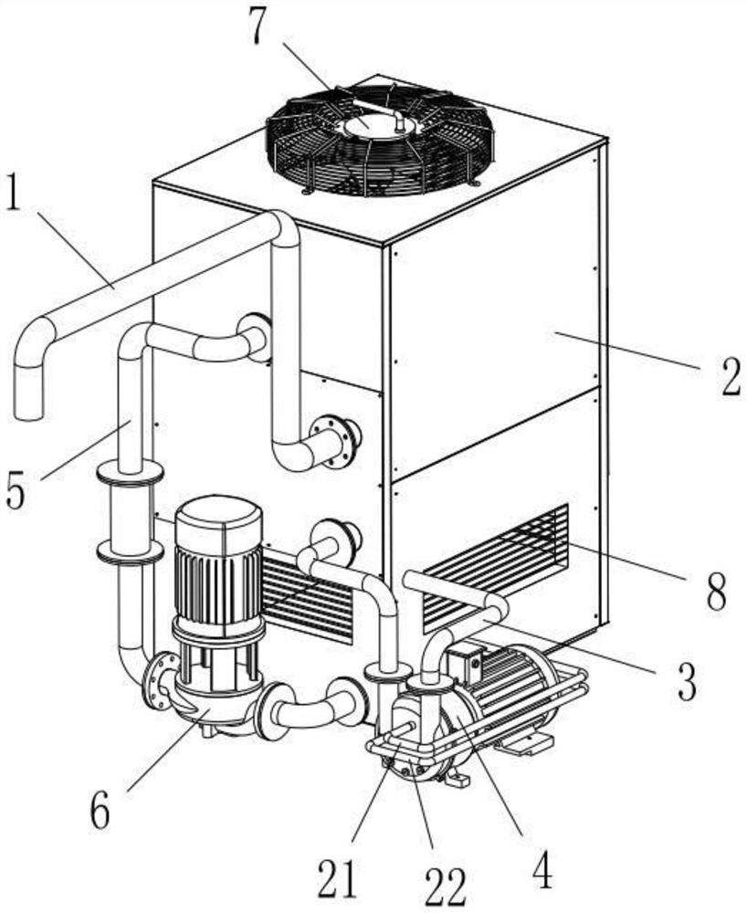
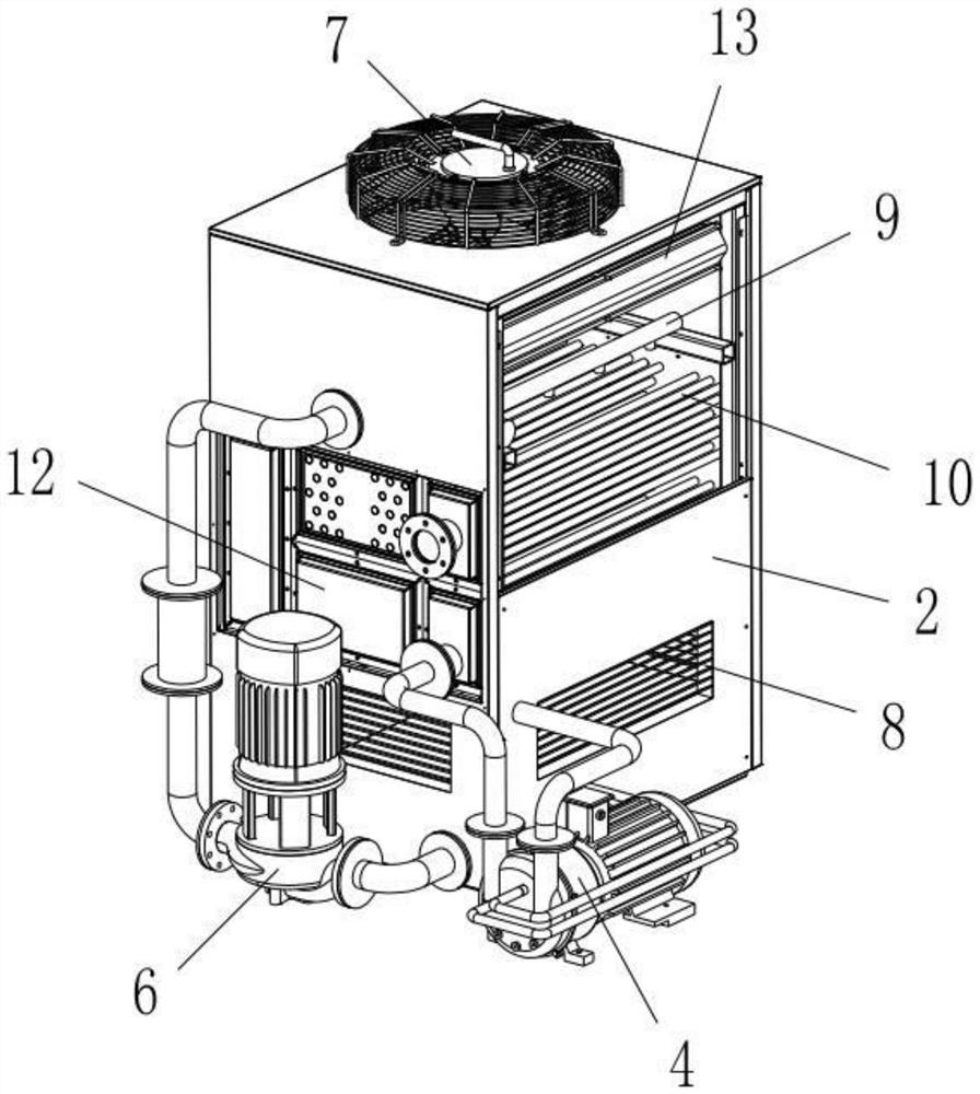
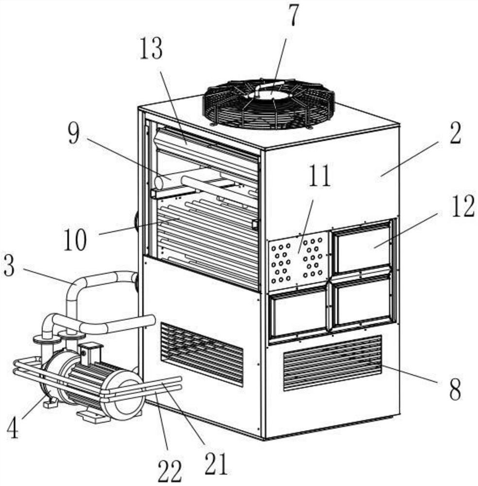
[0016] like Figure 1-3 As shown, a waste gas treatment equipment for garbage treatment equipment according to the present invention includes an intake pipeline 1 , a fume hood 2 , an exhaust pipeline 3 , a vacuum pump 4 , a spray pipeline 5 and a spray pump 6 .

[0017] The top of the fume hood 2 is provided with an exhaust fan 7, the lower part of the fume hood 2 is provided with air inlets 8, and the air inlet 8 is provided with water blocking louvers; the fume hood 2 is provided with a spray device 9 and a plurality of ventilation pipes 10. The ventilation pipe mounting plates 11 are fixedly installed on both sides of the fume hood 2 , and the two ends of the ventilation pipe 10 are respectively fixed on the ventilation pipe mounting plates 11 on both sides of the fume hood 2 .

[0018] A plurality of detachable sealing covers 12 a...


PUM


Abstract

The invention relates to waste gas treatment equipment for garbage treatment equipment. The waste gas treatment equipment comprises a gas inlet pipeline, a ventilation cabinet, a gas exhaust pipeline, a vacuum pump, a spraying pipeline and a spraying pump, according to the scheme, the structure of the waste gas treatment equipment is optimally designed, waste gas in the ventilation pipe is cooled in a ventilation and spraying air-cooling and water-cooling combined mode, the two ends of the ventilation pipe form an S-shaped channel through the detachable sealing covers, after long-time use, the sealing covers can be detached, the ventilation pipe is directly flushed, and the waste gas treatment equipment is convenient to use. The maintenance is simple and convenient, and the cabinet body does not need to be massively disassembled; and finally, the waste gas can be introduced into the cabinet, and is further directly sprayed, so that the waste gas is effectively and thoroughly treated. And the vacuum pump can form water ring cooling by using water in the cabinet body, and an external cooling water pipe is not needed, so that resources are saved, and the use cost is reduced.

Description

technical field [0001] The invention relates to a waste gas treatment equipment used for garbage treatment equipment, and belongs to the technical field of environmental protection equipment. Background technique [0002] With the strengthening of people's awareness of environmental protection, more and more garbage treatment equipment has been put into people's living facilities. Through garbage treatment equipment, kitchen waste and other garbage can be turned into fertilizers and other materials, which can be recycled. Waste gas will be generated in the process of garbage disposal. At present, most of the treatment methods are to directly discharge the waste gas into the air; but this will pollute the air and cause discomfort to the surrounding staff. [0003] In order to solve this problem, some garbage treatment equipment on the market is currently equipped with an exhaust gas treatment mechanism, which realizes exhaust gas purification by spraying, but its structural d...

Claims


Application Information

Patent Timeline
Patent Type & Authority Applications(China)
IPC IPC(8): B01D47/06
CPCB01D47/06Y02P70/10
Inventor 顾林江
Owner 苏州傲龙环保科技有限公司
Why Eureka
Try Eureka