Carbon capture system based on capacitive deionization technology

A capacitive deionization and carbon capture technology, applied in the field of carbon capture systems, can solve the problems of low capacitor power, increased energy consumption, toxic and harmful amines, etc.

Active Publication Date: 2022-08-09
JIANGSU UNIV OF SCI & TECH
View PDF11 Cites 0 Cited by
  • Summary
  • Abstract
  • Description
  • Claims
  • Application Information

AI Technical Summary

Problems solved by technology

Amine absorbents are certainly a good CO 2 Adsorb the solvent, but the amine is a toxic and harmful compound, and the subsequent analysis of CO 2 It still needs to use a certain high temperature, which again increases a lot of energy consumption
In recent years, capacitive deionization technology (CDI), which has been applied in the field of seawater desalination, has entered our field of vision. Capacitive deionization technology and other absorbents are used to capture CO in exhaust gas. 2 The temperature will no longer be too high, and the power consumed by the capacitor is also low, so the CDI captures CO 2 not a viable option

Method used


Image

  • Carbon capture system based on capacitive deionization technology
  • Carbon capture system based on capacitive deionization technology
  • Carbon capture system based on capacitive deionization technology

Examples


Embodiment Construction

[0023] The technical solutions of the present invention will be further described below with reference to the accompanying drawings.

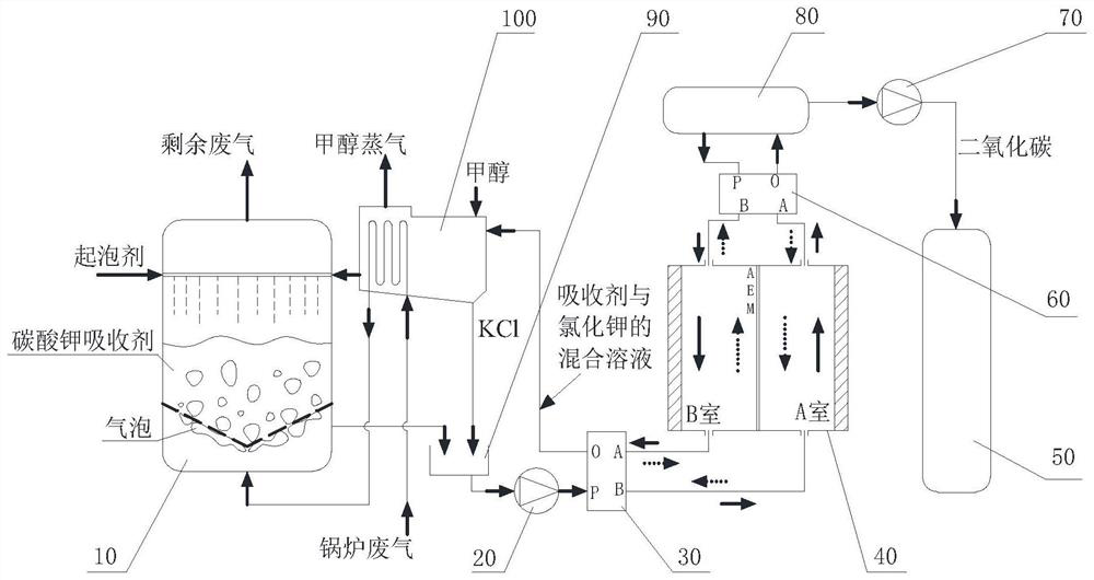
[0024] like figure 1 As shown, the present invention includes an absorption chamber 10, a drive pump 20, a first solenoid valve 30, a capacitive deionization device 40, a storage tank 50, a second solenoid valve 60, a fan 70, a flash tank 80, a buffer chamber 90, a separation chamber 100.

[0025] The boiler exhaust gas inlet is connected to the coil inlet 162 of the separation chamber 100, the coil outlet 161 of the separation chamber 100 is connected to the exhaust gas inlet 12 at the bottom of the absorption chamber 10, the top of the absorption chamber 10 is provided with the remaining exhaust gas outlet 16, and the outlet 170 of the separation chamber 100 is connected to the absorption chamber 10 side inlet 15 is communicated. A foaming agent inlet 17 is provided above the foaming agent inlet and the absorption chamber 10, the absorbent ...


PUM


Abstract

The device comprises an absorption chamber, a capacitive deionization device, a mixing tank and a separation chamber, the capacitive deionization device comprises a chamber A and a chamber B, a boiler waste gas input port is communicated with an inlet of a coil pipe of the separation chamber, and an outlet of the coil pipe of the separation chamber is communicated with the absorption chamber. An absorbent outlet of the absorption chamber and a potassium chloride precipitation outlet of the separation chamber are respectively communicated with the mixing tank, the bottom of the mixing tank is communicated with a chamber A of the capacitive deionization device, a chamber B of the capacitive deionization device is communicated with a doped absorbent solution inlet of the separation chamber, and the chamber A and the chamber B of the capacitive deionization device are respectively communicated with the flash tank. And the flash tank is connected with a storage tank for storing carbon dioxide. According to the invention, the capacitive deionization technology is changed from traditional intermittent work to continuous work in a carbon capture system.

Description

technical field [0001] The invention relates to the field of carbon capture, in particular to a carbon capture system for adjusting pH based on potassium carbonate absorbent combined with capacitive deionization technology. Background technique [0002] There are many CO 2 capture process, but for CO in boiler exhaust gas 2 Capture almost always involves amine absorbents. Amine absorbent is certainly a good CO 2 Adsorbs solvents, but amines are toxic and harmful compounds, and CO will be desorbed later 2 It is necessary to use a certain high temperature, which again increases a lot of energy consumption. In recent years, capacitive deionization technology (CDI), which is applied to the field of seawater desalination, has come into our field of vision. Capacitive deionization technology is used in conjunction with other absorbents to capture CO in exhaust gas. 2 The temperature will not be too high, and the power consumed by the capacitor is also lower, so the CDI captur...

Claims


Application Information

Patent Timeline
Patent Type & Authority Applications(China)
IPC IPC(8): B01D53/78B01D53/62
CPCB01D53/78B01D53/62Y02C20/40
Inventor 刘锐何泓曦何思齐姚寿广沈妍许啸姚江何晓崐
Owner JIANGSU UNIV OF SCI & TECH
Why Eureka
Try Eureka