Automatic yarn hanging robot and control method thereof
A technology of robot and driving mechanism, which is applied in the directions of overall factory control, thin material handling, and conveying filamentous materials. The effect of designing work, improving work efficiency, and saving labor costs
- Summary
- Abstract
- Description
- Claims
- Application Information
AI Technical Summary
Problems solved by technology
Method used
Image

Examples
Embodiment 1
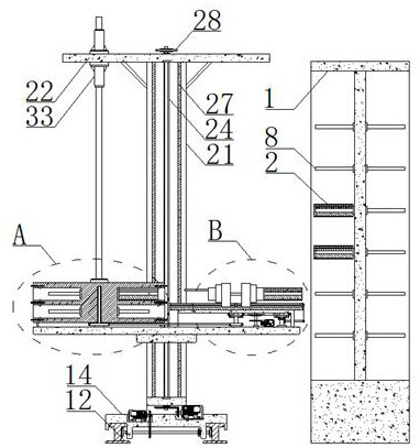
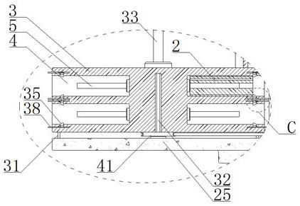
[0035] see figure 1 , an automatic yarn hanging robot, which is installed with the yarn hanger 1, and includes a lateral travel mechanism, a longitudinal travel mechanism, a storage mechanism, and a retractable and hanging mechanism. The lateral travel mechanism is arranged along the length of the yarn hanger 1. All of them are installed on the movable parts of the longitudinal travel mechanism and are used to hoist and store the bobbin 2. The storage mechanism includes: a storage tray 3 rotatably installed on the longitudinal travel mechanism, a storage cavity 4 evenly opened on the outer side wall of the rotating tray in a circular array, and a storage shaft 5 fixedly installed in the storage cavity 4 and arranged along the diameter direction of the storage tray 3. ; The shaft center of the bobbin 2 is provided with an insertion hole 6 that is nested with the storage shaft 5, and the insertion hole 6 is nested with the yarn hanging rod 7 on the yarn hanger 1.
[0036] The r...
Embodiment 2
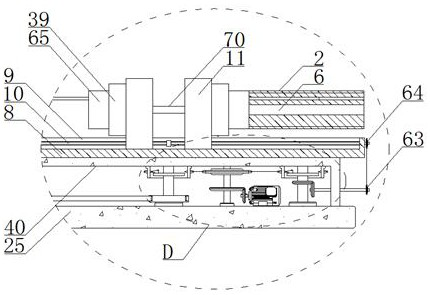
[0039] see figure 1 , 6 -7, the lateral travel mechanism involved in Embodiment 1 will be further described. The transverse traveling mechanism includes: two sets of traveling guide rails 12 fixed on the horizontal ground and kept parallel to the length of the yarn hanger 1; The traveling seat 14 on the traveling guide rail 12 is rotatably mounted on the traveling seat 14 to maintain a parallel arrangement of multiple sets of transmission shafts 15 , and the driving gears 16 fixed on both ends of the transmission shaft 15 and in mesh with the rack 13 are fixedly installed on the The first motor 17 on the traveling seat 14 and linked with each group of transmission shafts 15 ; the longitudinal traveling mechanism is matched and installed on the traveling seat 14 .
[0040] By controlling the operation of the first motor 17, each group of transmission shafts 15 and the driving gear 16 fixed on the transmission shaft 15 are driven to rotate, thereby driving the travel seat 14 t...
Embodiment 3
[0044] see figure 1 , 6 -7, and in conjunction with Embodiment 2, the longitudinal travel mechanism involved in Embodiment 1 will be further described. The longitudinal travel mechanism is installed on the movable part of the transverse travel mechanism. The longitudinal travel mechanism includes: two sets of installation columns 21 fixed on the travel seat 14 in the vertical direction and kept in parallel arrangement, respectively fixed to the upper and lower parts of the installation column 21. The upper connecting plate 22 and the lower connecting plate 23 at the ends are rotatably installed between the upper connecting plate 22 and the lower connecting plate 23 and arranged in the vertical direction. The adjusting screw 24 maintains the screwed lifting seat 25, and is fixedly installed on the traveling seat 14 and is linked with the second motor 26 of the adjusting screw 24;
[0045] By controlling the second motor 26 to work, the adjusting screw 24 is driven to rotate, ...
PUM
 Abstract
Description
Claims
Application Information
 - R&D
- Intellectual Property
- Life Sciences
- Materials
- Tech Scout
- Unparalleled Data Quality
- Higher Quality Content
- 60% Fewer Hallucinations
Browse by: Latest US Patents, China's latest patents, Technical Efficacy Thesaurus, Application Domain, Technology Topic, Popular Technical Reports.
© 2025 PatSnap. All rights reserved.Legal|Privacy policy|Modern Slavery Act Transparency Statement|Sitemap|About US| Contact US: help@patsnap.com