Sealing structure for bearing cavity of turbine rotor of core engine

A technology of turbine rotor and core engine, applied in mechanical equipment, engine components, machines/engines, etc., can solve the problems of core engine performance parameter interference, reduce stability and reliability, difficult processing and installation, and achieve simple and convenient processing. , The effect of reducing the change of the original structure and reducing the difficulty of sealing

Active Publication Date: 2022-08-09
成都中科翼能科技有限公司
View PDF15 Cites 4 Cited by
  • Summary
  • Abstract
  • Description
  • Claims
  • Application Information

AI Technical Summary

Problems solved by technology

However, due to the lack of domestic gas turbine core machine test data, it is generally used to remove the low-pressure turbine rotor and connect the modified low-pressure shaft cylinder with the turbine fulcrum frame to perform simple processing on the core machine, that is, to start the core machine test, so The method will retain many sealed structures and low-pressure bearings, and these structures are likely to reduce the stability and reliability of the operation due to the complex structure during the test, and the core machine only has high-pressure compressors to compress air, and its internal bleed air pressure is far away. Smaller than the whole machine, these sealing structures cannot meet the sealing requirements only by internal bleed air, and at this time it is necessary to connect pipelines for external bleed air; this will not only inevitably lead to complicated structures, increased costs, and difficulties in processing and installation. A series of problems will also cause unpredictable interference to the performance parameters of the core machine in the test

Method used


Image

  • Sealing structure for bearing cavity of turbine rotor of core engine
  • Sealing structure for bearing cavity of turbine rotor of core engine
  • Sealing structure for bearing cavity of turbine rotor of core engine

Examples


Embodiment 1

[0036] The core machine mainly includes high-pressure compressor components, combustion chamber and high-pressure turbine components, which work at extremely high temperatures and bear huge loads. When the gas turbine core machine test is performed, the turbine components will often retain the high-pressure turbine rotor 8 and the turbine fulcrum frame 12, and remove the low-pressure turbine rotor 18. In the prior art, after the low-pressure turbine rotor 18 is disassembled, a method of connecting the modified low-pressure shaft barrel to the turbine fulcrum frame 12 is often used to simply process the core machine, and then start the core machine test. Many sealing structures and low-pressure bearings are retained. These complex structures reduce the stability and reliability of operation, and the core machine only has compressed air from a high-pressure compressor, and its internal bleed air pressure is much lower than that of the whole machine. Therefore, these sealing struc...

Embodiment 2

[0050] When the sealing structure is not used for the high-pressure turbine rotor 8 and the low-pressure turbine rotor 18 described in Embodiment 1, but is applied to core machines of other types or structures for sealing, the sealing structure can also be used for sealing.

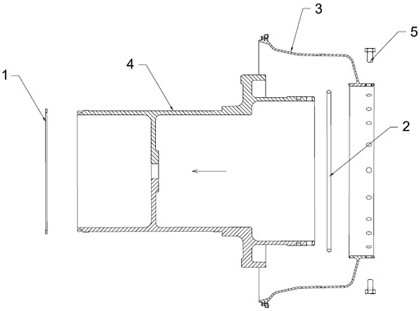
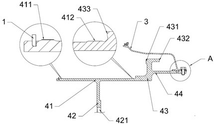
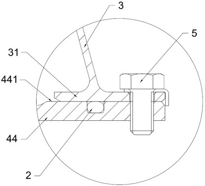
[0051] Specifically, the sealing structure in this embodiment includes a rear shaft section 44, an installation disk portion 43 and a front shaft section 41; the rear shaft section 44, the installation disk portion 43 and the front shaft section 41 extend from the rear to the rear of the core machine. The front side of the outer edge of the mounting disc portion 43 has a front pressing surface 431; the oil cavity sealing bushing 3 is in the shape of a cone ring, and the rear sides of the oil cavity sealing bushing 3 are respectively sealed and connected The rear shaft section 44 is formed with a second oil cavity 14 between the oil cavity sealing bushing 3, the sealing shaft barrel 4 and the original struc...


PUM


Abstract

The invention belongs to the technical field of technical gas turbines, and particularly relates to a sealing structure for a bearing cavity of a turbine rotor of a core engine, which is used for replacing a low-pressure turbine rotor to be connected with the core engine and comprises a sealing shaft barrel and an oil cavity sealing bushing, the sealing shaft barrel comprises a rear shaft section, a mounting disc part and a front shaft section; the rear shaft section, the mounting disc part and the front shaft section are arranged in the direction of the core machine from back to front; the front shaft section can extend into the long labyrinth ring, so that labyrinth seal is formed by the long labyrinth ring and the high-pressure turbine shaft; the front abutting face of the mounting disc part can abut against the end face of the rear side of the bearing oil injection ring, so that the third oil cavity is closed. And a second oil cavity is formed among the oil cavity sealing bushing, the turbine fulcrum frame and the sealing shaft barrel. According to the scheme, the sealing structure can be matched with the structure of the core machine and has the advantages of being simple in structure, good in manufacturability and low in cost; and a sealing mode of combining different seals is adopted, so that the sealing difficulty is reduced, and the change of an original structure is reduced.

Description

technical field [0001] The invention belongs to the technical field of technical gas turbines, and in particular relates to a sealing structure for a bearing cavity of a turbine rotor of a core machine. Background technique [0002] A gas turbine is an internal combustion power machine that converts the energy of gas into useful work. It is widely used in the field of civil power generation or as a power device in aircraft or large ships. The working process of the gas turbine is as follows: the compressor continuously sucks in air from the atmosphere and compresses the air; the air before compression enters the combustion chamber, and mixes with the gas injected into the combustion chamber before being combusted to become high-temperature gas, and then the high-temperature gas flows into the combustion chamber. It expands to the gas turbine to do work, and uses high-temperature gas to drive the turbine to rotate with the compressor; the gas turbine is a device with good cle...

Claims


Application Information

Patent Timeline
Patent Type & Authority Applications(China)
IPC IPC(8): F01D25/16F01D25/18F01D5/02F01D11/04
CPCF01D25/16F01D25/18F01D5/02F01D11/04Y02E10/20
Inventor 赵月彬王鸣杨惠高原方圆李冰雁齐振彪
Owner 成都中科翼能科技有限公司
Why Eureka
Try Eureka