Eureka AIR delivers breakthrough ideas for toughest innovation challenges, trusted by R&D personnel around the world.

Efficient quartz sand drying machine

A quartz sand drying and high-efficiency technology, applied in the direction of dryer, drying, dryer combination, etc., can solve the problems of reduced work efficiency, inconvenient dredging, inlet blockage, etc., and achieve the effect of improving work efficiency and convenient dredging

Inactive Publication Date: 2022-08-09
江苏火焰山干燥技术有限公司
View PDF0 Cites 0 Cited by
  • Summary
  • Abstract
  • Description
  • Claims
  • Application Information

AI Technical Summary

Problems solved by technology

[0003] However, the existing quartz sand dryers tend to cause inlet blockage when feeding materials, and are not easy to dredge, thereby reducing work efficiency; and in the existing dryers, there are still some wet quartz particles in the dried quartz sand Sand, so it needs to be dried again, resulting in reduced work efficiency

Method used


Image

  • Efficient quartz sand drying machine

Examples


Embodiment 1

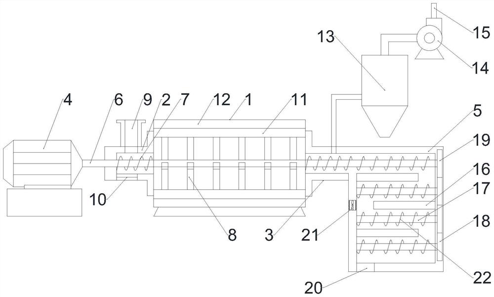
[0020] see figure 1 , the present invention provides a technical solution: a high-efficiency quartz sand dryer, comprising a drying cylinder 1, the left and right ends of the drying cylinder 1 are respectively provided with a feeding cylinder 2 and a discharging cylinder 3, and the other end of the feeding cylinder 2 is provided with a motor 4. The other end of the discharge cylinder 3 is connected to the air drying cylinder 5, the output end of the motor 4 is connected to the main shaft 6, and the main shaft 6 passes through the feeding cylinder 2, the drying cylinder 1, the discharging cylinder 3 and the air drying cylinder 5 in turn, and the main shaft 6 is located in the feeding cylinder. The parts in the drum 2 , the discharging drum 3 and the air drying drum 5 are provided with screw conveying blades 7 , and the part of the main shaft 6 in the drying drum 1 is provided with stirring blades 8 .

Embodiment 2

[0022] see figure 1 , the present invention provides a technical solution: a high-efficiency quartz sand dryer, comprising a drying cylinder 1, the left and right ends of the drying cylinder 1 are respectively provided with a feeding cylinder 2 and a discharging cylinder 3, and the other end of the feeding cylinder 2 is provided with a motor 4. The other end of the discharge cylinder 3 is connected to the air drying cylinder 5, the output end of the motor 4 is connected to the main shaft 6, and the main shaft 6 passes through the feeding cylinder 2, the drying cylinder 1, the discharging cylinder 3 and the air drying cylinder 5 in turn, and the main shaft 6 is located in the feeding cylinder. The parts in the drum 2 , the discharging drum 3 and the air drying drum 5 are provided with screw conveying blades 7 , and the part of the main shaft 6 in the drying drum 1 is provided with stirring blades 8 .

[0023] The upper end of the feeding cylinder 2 is provided with a feeding po...


PUM


Abstract

The efficient quartz sand drying machine comprises a drying cylinder, a feeding cylinder and a discharging cylinder are arranged at the left end and the right end of the drying cylinder correspondingly, a motor is arranged at the other end of the feeding cylinder, the other end of the discharging cylinder is connected with an air drying cylinder, the output end of the motor is connected with a main shaft, and the main shaft sequentially penetrates through the feeding cylinder, the drying cylinder, the discharging cylinder and the air drying cylinder; spiral conveying blades are arranged on the part, located in the feeding cylinder, the discharging cylinder and the air drying cylinder, of the main shaft, and stirring blades are arranged on the part, located in the drying cylinder, of the main shaft. The quartz sand is subjected to secondary air drying after being dried, so that the problem that some moist quartz sand still exists after the traditional quartz sand is dried by a dryer is solved, and the working efficiency is improved; spiral conveying blades are arranged on the parts, located in the feeding cylinder, the discharging cylinder and the air drying cylinder, of the main shaft, on one hand, the quartz sand is conveyed, and on the other hand, the spiral conveying blades can effectively prevent the quartz sand from blocking the feeding cylinder; the dredging door is arranged at the lower end of the feeding cylinder, so that dredging is facilitated when the feeding cylinder is blocked.

Description

technical field [0001] The invention relates to the technical field of dryers, in particular to a high-efficiency quartz sand dryer. Background technique [0002] Quartz sand is a non-metallic mineral. It is a hard, wear-resistant and chemically stable silicate mineral. Its main mineral component is SiO2. The color of quartz sand is milky white or colorless and translucent, with a hardness of 7 , Quartz sand is an important industrial mineral raw material. In daily use, a quartz sand dryer needs to be used to dry and process the quartz sand. [0003] However, the existing quartz sand dryer is easy to cause inlet blockage when feeding, and it is inconvenient to dredge, thereby reducing the work efficiency; and in the existing dryer, the dried quartz sand still has some wet quartz Sand, so it needs to be dried again, resulting in reduced work efficiency. SUMMARY OF THE INVENTION [0004] The purpose of the present invention is to provide a high-efficiency quartz sand dryer...

Claims


Application Information

Patent Timeline
Patent Type & Authority Applications(China)
IPC IPC(8): F26B20/00F26B11/16F26B17/20F26B21/00F26B23/00F26B25/00F26B25/02
CPCF26B20/00F26B11/16F26B17/20F26B21/004F26B23/00F26B25/002F26B25/005F26B25/02
Inventor 辅玲柏林霞朱汉卿
Owner 江苏火焰山干燥技术有限公司
Why Eureka
Eureka Blog
Learn More