
Shell pass exhaust and pollution discharge structure suitable for vertical shell-and-tube waste boiler heat exchanger

A shell-and-tube heat exchanger technology, applied in the direction of heat exchanger shell, indirect heat exchanger, heat exchanger type, etc., can solve the local failure of the waste boiler heat exchanger, and can only be as close to the end of the tube sheet as possible. , can not be fully cooled, etc., to achieve the effect of good sewage effect, easy processing, and no difficulty in manufacturing

Pending Publication Date: 2022-08-09
THE CHALLENGE PETROCHEM MACHINERY CORP
View PDF0 Cites 0 Cited by
  • Summary
  • Abstract
  • Description
  • Claims
  • Application Information

AI Technical Summary

Problems solved by technology

[0004] As far as the structure of the waste boiler heat exchanger is widely used at present, the shell side is a single-layer shell structure. When the shell side inlet and outlet are set, due to the limitation of the connection structure, the design needs to ensure the opening and reinforcement range, and the manufacturing needs to have enough welding operations. space, so it can only be as close as possible to the end of the tube sheet
Therefore, in the existing waste boiler heat exchanger, due to the limitation of the inlet and outlet positions of the shell side, the water in the shell side cannot fill the entire shell during operation, and the unfilled position will be filled with high-temperature steam at the top tube plate position of the shell side. , the side of the tube sheet close to the shell side and the connection between the tube sheet and the heat exchange tube will not be sufficiently cooled, which greatly increases the hidden danger of local failure caused by the local high temperature of the shell side of the waste boiler heat exchanger. For vertical heat exchangers, it is a fatal weakness. Once it fails, it will be difficult to repair on the one hand, and the replacement cycle will be longer on the other hand.

Method used


Image

  • Shell pass exhaust and pollution discharge structure suitable for vertical shell-and-tube waste boiler heat exchanger
  • Shell pass exhaust and pollution discharge structure suitable for vertical shell-and-tube waste boiler heat exchanger
  • Shell pass exhaust and pollution discharge structure suitable for vertical shell-and-tube waste boiler heat exchanger

Examples


Embodiment Construction

[0037] The present invention will be described in detail below with reference to specific embodiments and accompanying drawings.

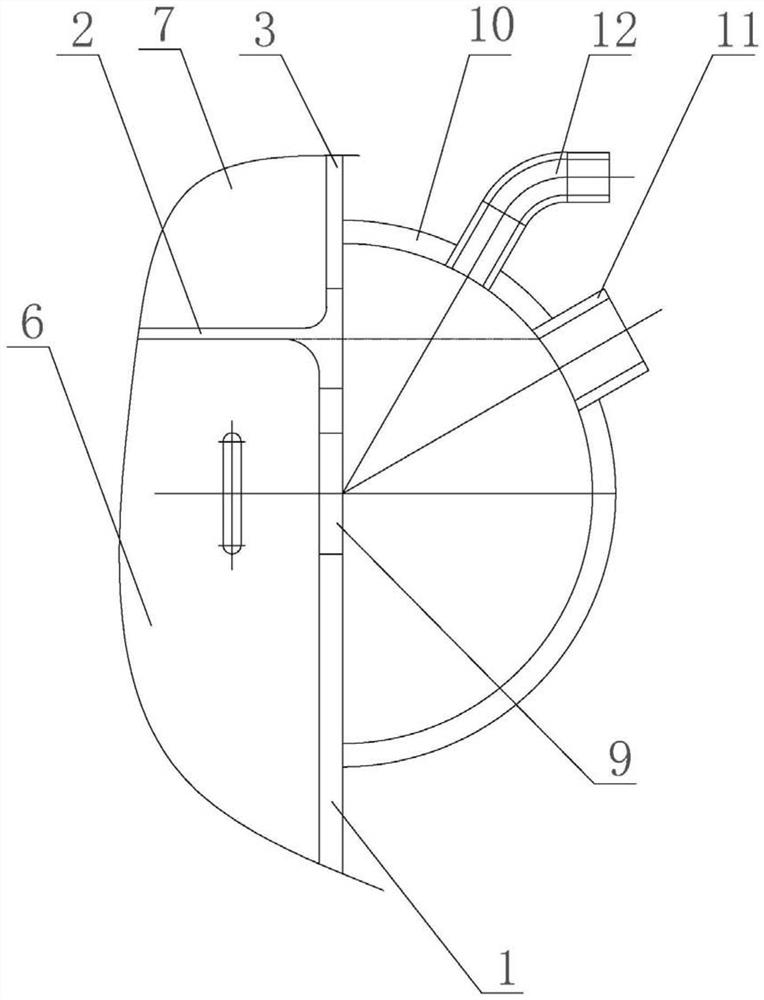
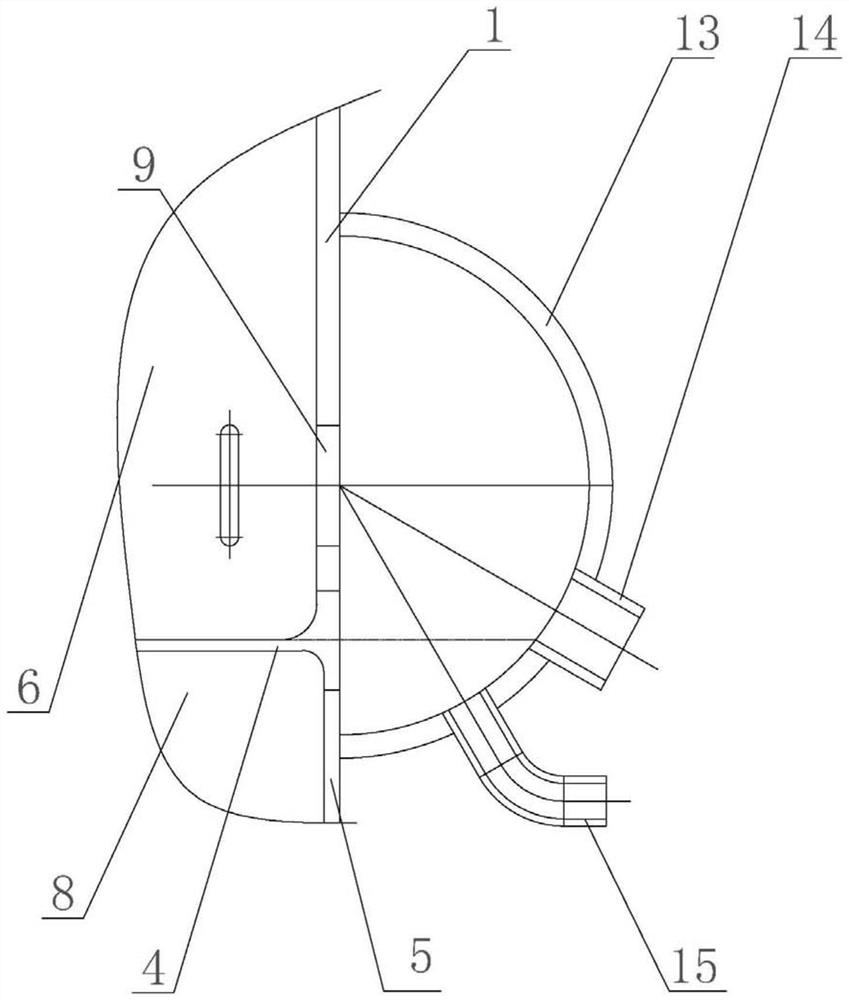
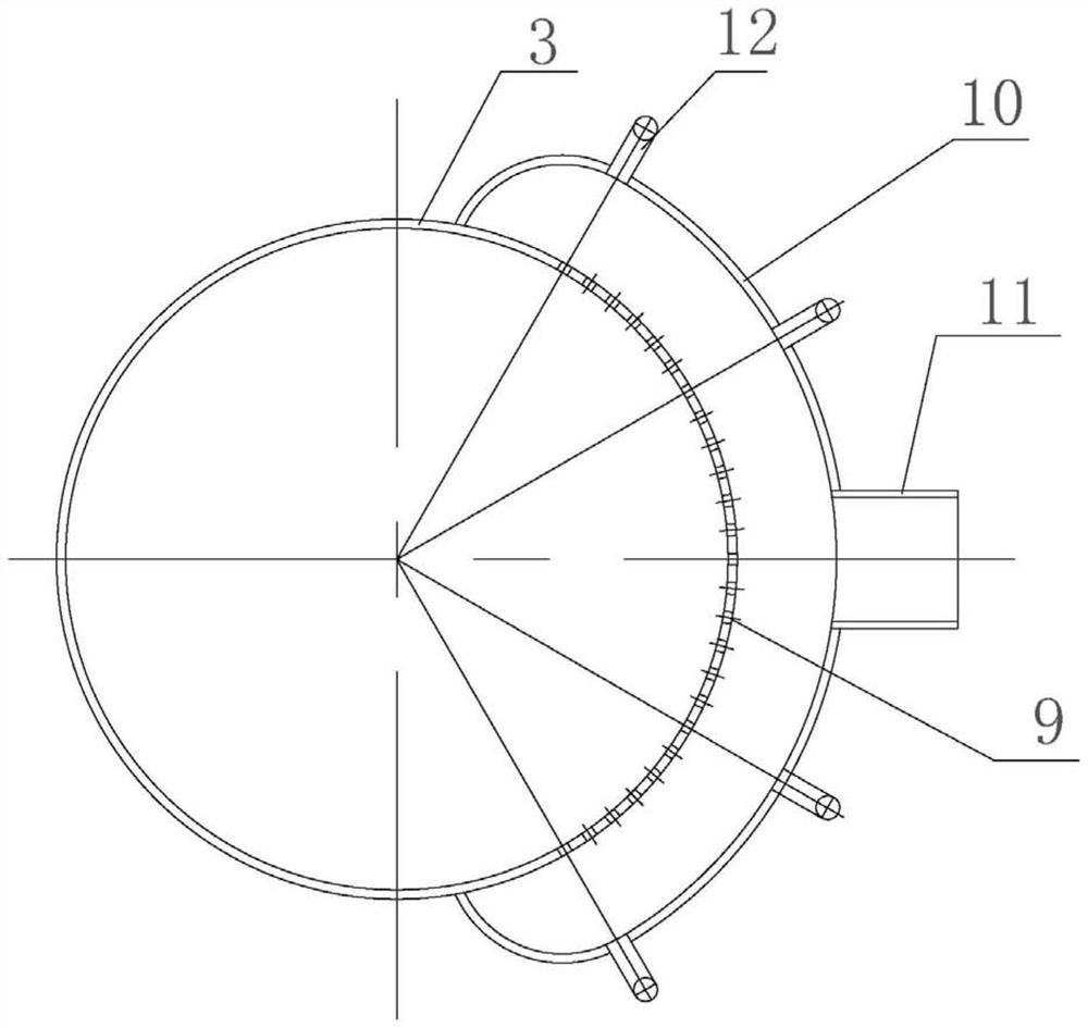
[0038] The shell-side exhaust and sewage discharge structure suitable for the vertical shell-and-tube waste boiler heat exchanger in this embodiment, such as figure 1 and figure 2 As shown, it includes a shell 1, an upper tube sheet 2, an upper tube box 3, a lower tube sheet 4, a lower tube box 5 and a plurality of heat exchange tubes (not shown in the figure), the shell 1 is a cylindrical body, the upper The tube sheet 2 and the lower tube sheet 4 are respectively fixed to the two ends of the shell 1 and together form a shell side space 6, the upper pipe box 3 is fixed to the upper tube sheet 2 and together form an upper pipe side space 7, and the lower pipe box 5 is fixed to the lower tube plate 4 and together form a lower tube side space 8 . A plurality of heat exchange tubes are located in the shell-side space 6 , and their upper ends are co...


PUM


Abstract

The invention relates to the technical field of petrochemical equipment, in particular to a shell pass exhaust and pollution discharge structure suitable for a vertical shell-and-tube waste boiler heat exchanger, an upper flow guide cover communicated with a shell pass space is arranged on the outer side of the upper end part of a shell, is provided with a medium outlet, and extends across an upper tube plate to cover a part of an upper tube box; an exhaust port is formed in a position, higher than the bottom surface of the upper tube plate, of the upper flow guide cover; a lower flow guide cover communicated with the shell pass space is arranged on the outer side of the lower end of the shell, a medium inlet is formed in the lower flow guide cover, the lower flow guide cover extends and crosses the lower tube plate to cover part of the lower tube box, and a drain outlet is formed in the position, lower than the top face of the lower tube plate, of the lower flow guide cover. The whole shell pass is filled with shell pass media as much as possible through the upper and lower flow guide cover structures, the effect of balancing the temperature difference is achieved, the medium flow short circuit phenomenon possibly occurring due to the fact that a medium inlet and outlet is limited by a shell and tube plate connecting structure can be avoided, and local high-temperature failure of the connecting position of the shell and the tube plate is effectively avoided.

Description

technical field [0001] The invention relates to the technical field of petrochemical equipment, in particular to a shell-side exhaust and sewage discharge structure suitable for a vertical shell-and-tube type waste boiler heat exchanger. Background technique [0002] The shell-and-tube waste boiler heat exchanger currently used in petrochemical plants receives the cracked gas from the cracking furnace device at its tube side, and the inlet temperature of the tube side reaches 800-900°C under normal operating conditions, so the tube side is in a high temperature state; The shell side medium is water and steam, and the temperature is about 300 ℃ under normal operating conditions. Therefore, there is a very large temperature difference between the shell sides of the waste boiler heat exchanger. [0003] Based on the existence of large temperature difference, in the structural design of waste boiler heat exchanger, the tube sheet connecting the shell side of the tube generally ...

Claims


Application Information

Patent Timeline
Patent Type & Authority Applications(China)
IPC IPC(8): F28D7/16F28F9/02F28F17/00
CPCF28D7/1607F28F9/02F28F17/00Y02P20/129
Inventor 雷小娣黄嗣罗林进华刘恒
Owner THE CHALLENGE PETROCHEM MACHINERY CORP
Learn More