Round tube axial stress measuring device and method based on torsional mode ultrasonic guided waves

An axial stress, ultrasonic guided wave technology, applied in the direction of measuring devices, measuring forces, instruments, etc., can solve the problems of inability to measure the axial stress of the circular tube, application limitations, and the influence of the surface quality of components

Active Publication Date: 2022-08-09
ZHEJIANG UNIV
View PDF5 Cites 0 Cited by
  • Summary
  • Abstract
  • Description
  • Claims
  • Application Information

AI Technical Summary

Problems solved by technology

However, the X-ray diffraction method relies on the interaction between the X-ray beam and the crystal lattice of the material, and is easily affected by the surface quality of the component; the magnetoelastic method requires a magnetization process, and its application is limited by the magnetization conditions
[0003] At present, the ultrasonic force measurement method is mainly used to measure the residual stress in the welding area and the axial stress of high-strength bolts, rails and multi-strand wires, and it is still unable to measure the axial stress of circular pipes.
In addition, most of the existing ultrasonic force measurement methods use the longitudinal mode of ultrasonic waves, and there is no report on the method of measuring component stress using torsional mode ultrasonic waves.

Method used


Image

  • Round tube axial stress measuring device and method based on torsional mode ultrasonic guided waves
  • Round tube axial stress measuring device and method based on torsional mode ultrasonic guided waves
  • Round tube axial stress measuring device and method based on torsional mode ultrasonic guided waves

Examples


Embodiment Construction

[0025] The technical solutions in the embodiments of the present invention will be clearly and completely described below with reference to the accompanying drawings of the embodiments of the present invention. It should be noted that this embodiment is only a part of the embodiments of the present invention, and the technical parameters set in this embodiment are for reference only.

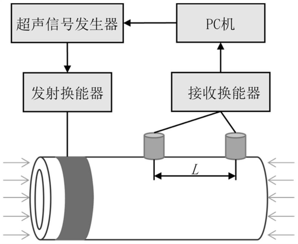
[0026] like figure 1 As shown, the present invention provides a device for measuring axial stress of a circular tube based on torsional mode ultrasonic guided waves, including a transmitting transducer, two receiving transducers, an ultrasonic generator and a PC;

[0027] The transmitting transducer is fixed at one end of the circular tube to be measured, and is used to excite the axially symmetric T(0,1) torsional mode ultrasonic guided wave transmitted along the axial direction of the circular tube and the particle vibration direction is tangential;

[0028] Two receiving transducers are fixe...


PUM

PropertyMeasurementUnit
diameteraaaaaaaaaa

Abstract

The invention discloses a circular tube axial stress measuring device and method based on torsional mode ultrasonic guided waves. Nondestructive testing of the axial stress of the steel pipe is crucial to structural health monitoring of in-service steel pipe components, and the device for measuring the axial stress of the circular pipe through torsional mode ultrasonic guided waves is developed on the basis of the acoustic elasticity theory. The device comprises a transmitting transducer and two receiving transducers. In the implementation process, the transmitting transducer located at one end of the circular tube to be measured excites expected waves, the expected waves are transmitted through the circular tube and received by the two receiving transducers with the fixed distance L, and the guided wave group velocity is obtained by recognizing the time interval when the two receiving transducers receive ultrasonic guided wave signals of the same mode. The specific detection method comprises the following steps: calibrating a linear relation between the axial stress of the circular tube and the guided wave group velocity through an experiment; and calculating the axial stress of the to-be-detected circular tube by detecting the guided wave group velocity of the to-be-detected circular tube according to the linear relation obtained through calibration.

Description

technical field [0001] The invention relates to an ultrasonic guided wave nondestructive stress measurement technology, in particular to a device and method for measuring the axial stress of a circular tube based on a torsional mode ultrasonic guided wave. Background technique [0002] Steel pipes are widely used as structural members, especially axially stressed members. Non-destructive measurement of axial stress is essential for structural health monitoring of in-service steel tubular members. There are many non-destructive stress measurement methods for steel components, such as resistance strain gauge sensing, optical fiber sensing, vibrating wire sensing, X-ray diffraction, magnetoelasticity and ultrasonic methods. However, among them, the resistance strain gauge, optical fiber sensor and vibrating wire sensor must be deployed in the unstressed state of the component in advance to measure the absolute stress of the component in service state. Other methods, including...

Claims


Application Information

Patent Timeline
Patent Type & Authority Applications(China)
IPC IPC(8): G01L1/25
CPCG01L1/255Y02E30/30
Inventor 许贤张怡朱思源韩劲松罗尧治
Owner ZHEJIANG UNIV
Why Eureka
Try Eureka