Current sensor and current sensor module

A current sensor and core technology, applied in the direction of measuring current/voltage, voltage/current isolation, instruments, etc., can solve the problems of miniaturization and unfavorable sensor size, reduce influence, suppress excessive flux leakage, and increase magnetoresistance Effect

Pending Publication Date: 2022-08-09
启东双赢电子科技有限公司
View PDF1 Cites 0 Cited by
  • Summary
  • Abstract
  • Description
  • Claims
  • Application Information

AI Technical Summary

Problems solved by technology

However, the disadvantages of this solution are: because the Hall sensor is placed at the opening of the U-shaped magnetic core, the distance between the Hall sensor and the two sides of the U-shaped magnetic core is relatively long, which will make the Hall sensor receive the magnetic core. (including wound compensation coils) yields magnetic field strength accuracy, and is also detrimental to miniaturization of the overall sensor volume

Method used


Image

  • Current sensor and current sensor module
  • Current sensor and current sensor module
  • Current sensor and current sensor module

Examples


Embodiment 1

[0036] see Figure 1 to Figure 5 , the present invention provides a kind of technical scheme:

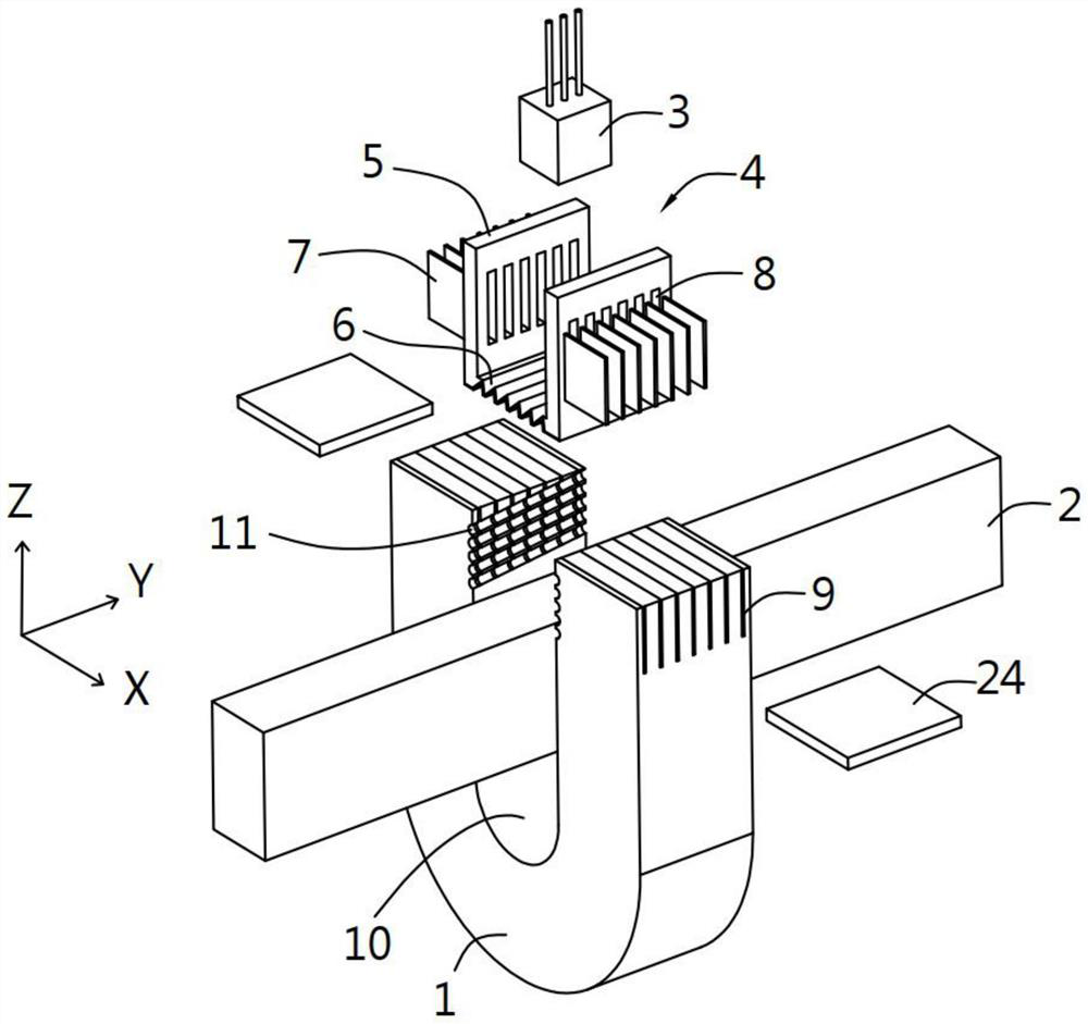
[0037] A current sensor, the sensor is mainly composed of the following components:

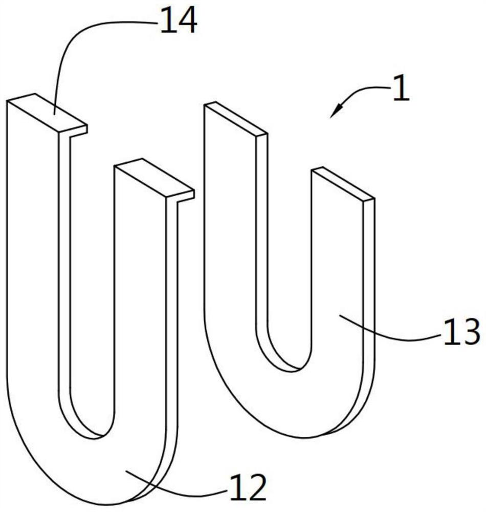
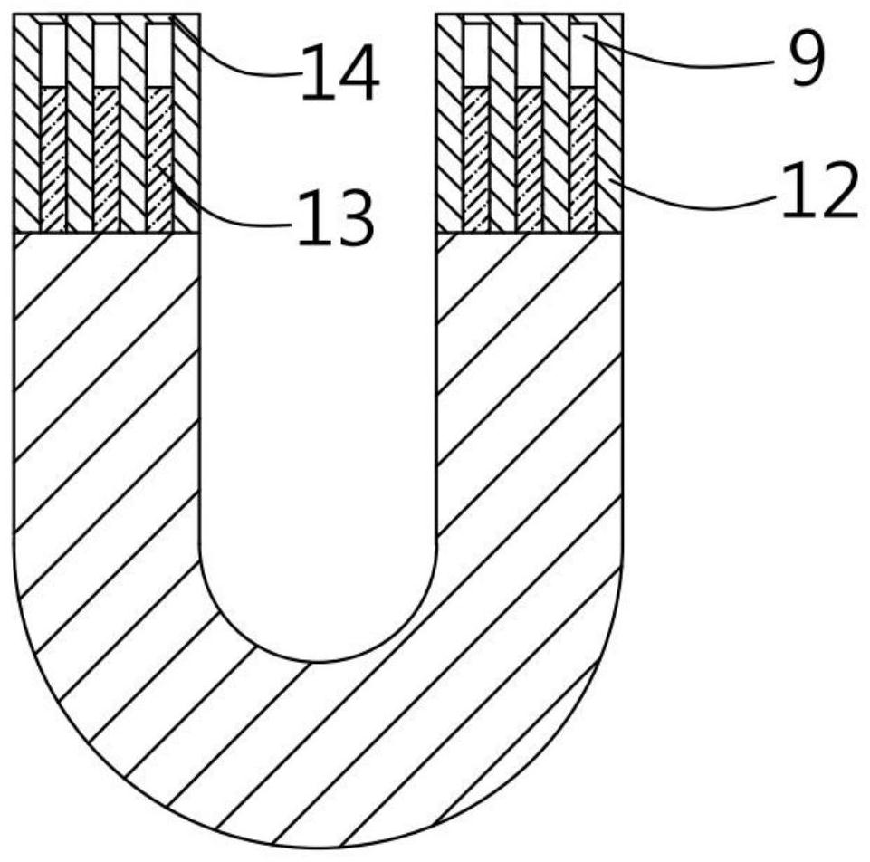
[0038] The core part 1 is mainly a U-shaped plate with a U-shaped groove 10 formed by stacking a plurality of first core parts 12 and second core parts 13 together;

[0039] The loop conductor 2 is inserted on the inner side of the U-shaped slot 10 of the above-mentioned core 1, and is used for the current to be measured to flow;

[0040] The resting portion 4 is arranged on the open side of the upper end of the aforementioned U-shaped groove 10;

[0041] The detection unit 3, installed in the aforementioned resting part 4, is used to detect the strength of the magnetic field;

[0042] a housing 20 for supporting the core 1, the loop conductor 2 and the detection unit 3;

[0043] A channel structure for supporting the resting portion 4 is formed on the upper end of the above-mentioned core port...

Embodiment 2

[0052] see Figure 6 to Figure 7 , the present invention provides a kind of technical scheme:

[0053] The structure of the second embodiment is basically the same as that of the first embodiment, the difference is that the channel structure includes the first core 12 or the second core located on the outermost side when the first core 12 and the second core 13 are stacked. The upper end of the part 13 has a resilient part 15, and the end of the core 1 except the first core part 12 or the second core part 13 located at the outermost side is a flush end 19, and the resilient part 15 is flush with the flush end 19. A region 18 for suppressing an increase in hysteresis loss is formed therebetween. The above-mentioned resting part 4 includes a springback distance 27 between the two springable parts 15 , and the detection unit 3 is stuck in the springback distance 27 . The aforementioned resilient portion 15 includes a straight portion 16 and an elastic curved portion 17. One end...


PUM


Abstract

The present invention provides a current sensor and a current sensor module. The current sensor comprises: a U-shaped plate having a U-shaped groove, the core of which is mainly formed by stacking a plurality of first core parts and second core parts; a loop conductor which is inserted on the inner side of the U-shaped groove of the core and through which a current to be measured flows; the placing part is arranged on the opening side of the upper end of the U-shaped groove; the detection unit is mounted in the shelving part and is used for detecting the intensity of the magnetic field; the shell is used for supporting the core part, the loop conductor and the detection unit; the upper end of the core part is provided with a channel structure which is used for supporting the shelving part and is used for dissipating heat and increasing magnetic flux when the detection unit detects the magnetic field intensity. According to the invention, the precision of the magnetic field intensity generated by the Hall sensor receiving magnetic core is improved, and the volume miniaturization of the whole sensor is also facilitated.

Description

technical field [0001] The invention relates to the technical field of current detection, in particular to a current sensor and a current sensor module. Background technique [0002] Current sensing is often used in electric power, automobile, automatic control and other fields to monitor current. In the application, the carrier fluid needs to pass through the detection hole of the sensor, and then is placed in the air gap of the magnetic ring through the Hall element (sensor), so that the Hall element will detect the change of the magnetic flux of the magnetic ring, and obtain the current value through calculation. [0003] In the prior art solution, Authorized Bulletin No. CN103884897B, discloses a current sensor and a method for manufacturing the current sensor, including: a housing, holding a bus bar to which current is applied and a magnetic core arranged around the bus bar; a circuit a plate fixed to the case in a state of being arranged to face the case; and a detect...

Claims


Application Information

Patent Timeline
Patent Type & Authority Applications(China)
IPC IPC(8): G01R19/00G01R15/20
CPCG01R19/0092G01R15/202
Inventor 尹志平
Owner 启东双赢电子科技有限公司
Why Eureka
Try Eureka