
Aluminum substrate, method for manufacturing same and LED light source with aluminum substrate

A manufacturing method and aluminum substrate technology, which is applied in the direction of multilayer circuit manufacturing, printed circuits connected with non-printed electrical components, electrical components, etc., can solve the problem of the difficulty in precisely controlling the heat conduction insulation layer, the reduction of heat conduction and heat dissipation effects, and the problems of heat conduction and insulation. Low layer reflectivity and other issues, to save semiconductor materials, improve production efficiency, and facilitate miniaturization

Inactive Publication Date: 2013-05-22
蚌埠德豪光电科技有限公司
View PDF6 Cites 2 Cited by
  • Summary
  • Abstract
  • Description
  • Claims
  • Application Information

AI Technical Summary

Problems solved by technology

This kind of aluminum substrate manufactured in the traditional way is difficult to use chips such as flip chip and vertical structure for integrated chip packaging due to the low precision of the electrodes formed on the circuit, and because of the low reflectivity of the heat-conducting insulating layer, it is not conducive to improving Chip light efficiency
[0004] At the same time, since it is difficult to accurately control the thickness of the thermally conductive insulating layer, in order to ensure its withstand voltage performance, a large margin must be left for the thickness of the insulating layer. Generally, the thickness of the insulating layer is 80-100 μm, so the thickness of the insulating layer is relatively large. The thermal conductivity of the resin is small, usually 1-2.0W / (m K), so its heat conduction and heat dissipation effects are greatly reduced

Method used


Image

  • Aluminum substrate, method for manufacturing same and LED light source with aluminum substrate
  • Aluminum substrate, method for manufacturing same and LED light source with aluminum substrate
  • Aluminum substrate, method for manufacturing same and LED light source with aluminum substrate

Examples


Embodiment Construction

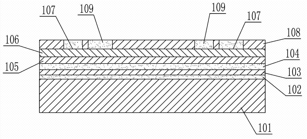
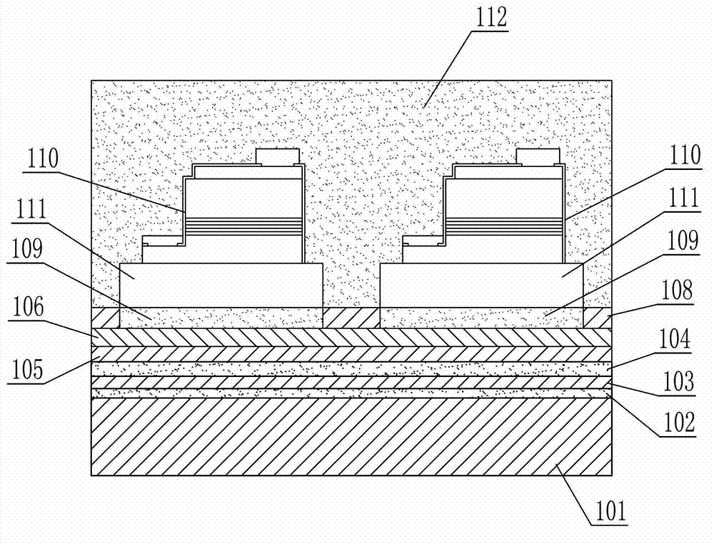
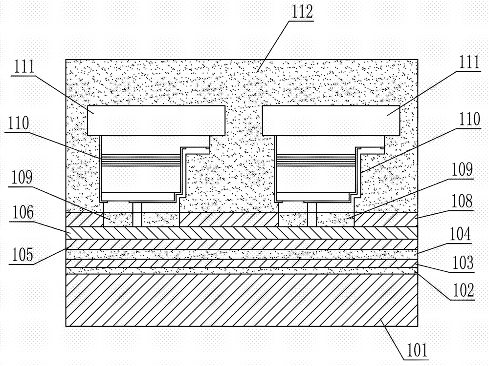
[0035] see figure 1 , the aluminum substrate shown in the figure includes an aluminum base plate 101, and the surface of the aluminum base plate 101 is sequentially provided with a conductive metal layer, a transparent metal oxide insulating layer 103, and a metal thin film layer 102; the conductive metal layer includes the first A conductive metal layer 105 and a second conductive metal layer 106 covering the first conductive metal layer 105, the second conductive metal layer 106 is provided with a conductive circuit (not shown) for connecting with the LED chip and fixing the LED Die-bonding functional area 107 of the chip.

[0036] Preferably, in order to prevent the first conductive metal layer 105 from peeling off from the metal oxide insulating layer 103, there is a metal buffer layer 104 on the metal oxide insulating layer 103, and the first conductive metal layer 105 is arranged on the metal buffer layer 104 on. The metal buffer layer 104 is made of tungsten, molybden...


PUM

PropertyMeasurementUnit
Thicknessaaaaaaaaaa
Thicknessaaaaaaaaaa
Thicknessaaaaaaaaaa

Abstract

The invention provides an aluminum substrate which comprises an aluminum bottom plate. Conducting metal layers, a metal oxide insulating layer and a metal film layer are sequentially arranged on the surface of the aluminum bottom plate from top to bottom, and a conducting circuit and crystal curing functional zones of LED chips are arranged on one of the conducting metal layers. The aluminum substrate has the advantages that the metal oxide insulating layer is good in radiating performance, so that the service life of each LED chip can be prolonged; and the LED chips can be connected with one another serially or in parallel and can be combined with one another after the LED chips and the substrate are packaged at one step, and can emit light and work after being directly connected with a driving circuit, accordingly, package processing steps are simplified, semiconductor materials and the cost are saved, and the production efficiency is improved greatly.

Description

technical field [0001] The invention relates to the technical field of LEDs, in particular to an aluminum substrate, a manufacturing method thereof and an LED light source using the aluminum substrate. Background technique [0002] The integration of multiple LED chips on a circuit board is called an integrated chip, and the LED integrated chip is being more and more widely used in LED lighting sources. Aluminum substrates are commonly used in LED integrated chips. The existing aluminum substrates for LED lighting generally use aluminum substrates as substrates, coat resin materials on the substrates as insulating layers, and then cover copper foil as conductive layers on the insulating layers. Because its insulating layer can withstand high voltage (>1500V / min) and the substrate has better heat dissipation, it is widely used in the field of LED light sources. [0003] Its application method is to screen-print and etch the copper foil to form a circuit on the aluminum ba...

Claims


Application Information

Patent Timeline
IPC IPC(8): H05K1/18H05K3/46H01L33/62H01L33/48
Inventor 王冬雷裴小明
Owner 蚌埠德豪光电科技有限公司
Learn More