
High-power output optical fiber coupler

A technology of output optical fiber and coupler, which is applied in the field of high-power output optical fiber coupler, which can solve the problems of reduced welding efficiency, easy corrosion of optical fiber joints, flattened optical fiber ends, etc., to achieve good sealing effect and improve thermal fusion efficiency , the effect of firm connection

Inactive Publication Date: 2022-08-09
鲍立新
View PDF0 Cites 0 Cited by
  • Summary
  • Abstract
  • Description
  • Claims
  • Application Information

AI Technical Summary

Problems solved by technology

[0002] When the existing optical fiber coupler is coupled, it is generally necessary to use a thermal fusion device to couple the optical fiber, and then take the optical fiber out of the thermal fusion device after the coupling is completed; and there are many optical fibers directly connected by the coupler, and the coupler is in the When connecting, it is difficult to align the end face of the optical fiber, and it is also difficult to flatten the end of the optical fiber, so that the end face of the optical fiber needs to be flattened before the butt joint, which reduces the welding efficiency, and it is easy to make the joint after welding. When the fiber optic connector is in water without protection, the fiber optic connector is easily corroded, especially the fiber optic connector in seawater is more severely corroded, which reduces the life of the fiber

Method used


Image

  • High-power output optical fiber coupler
  • High-power output optical fiber coupler
  • High-power output optical fiber coupler

Examples


Embodiment Construction

[0027] In order to make it easy to understand the technical means, creation features, achieved goals and effects of the present invention, the present invention will be further described below with reference to the specific embodiments.

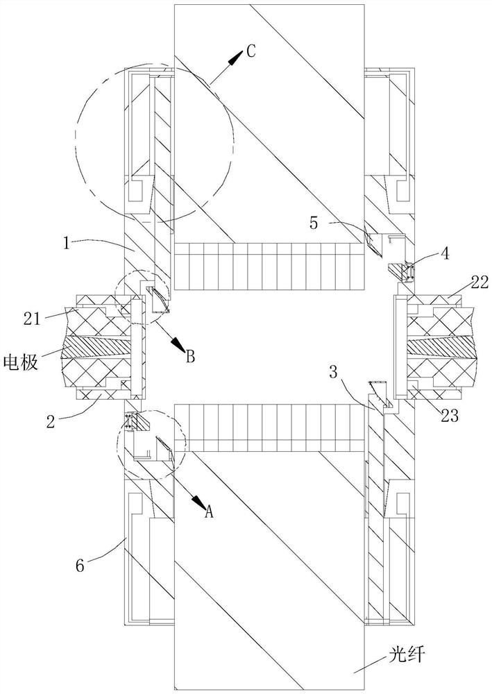
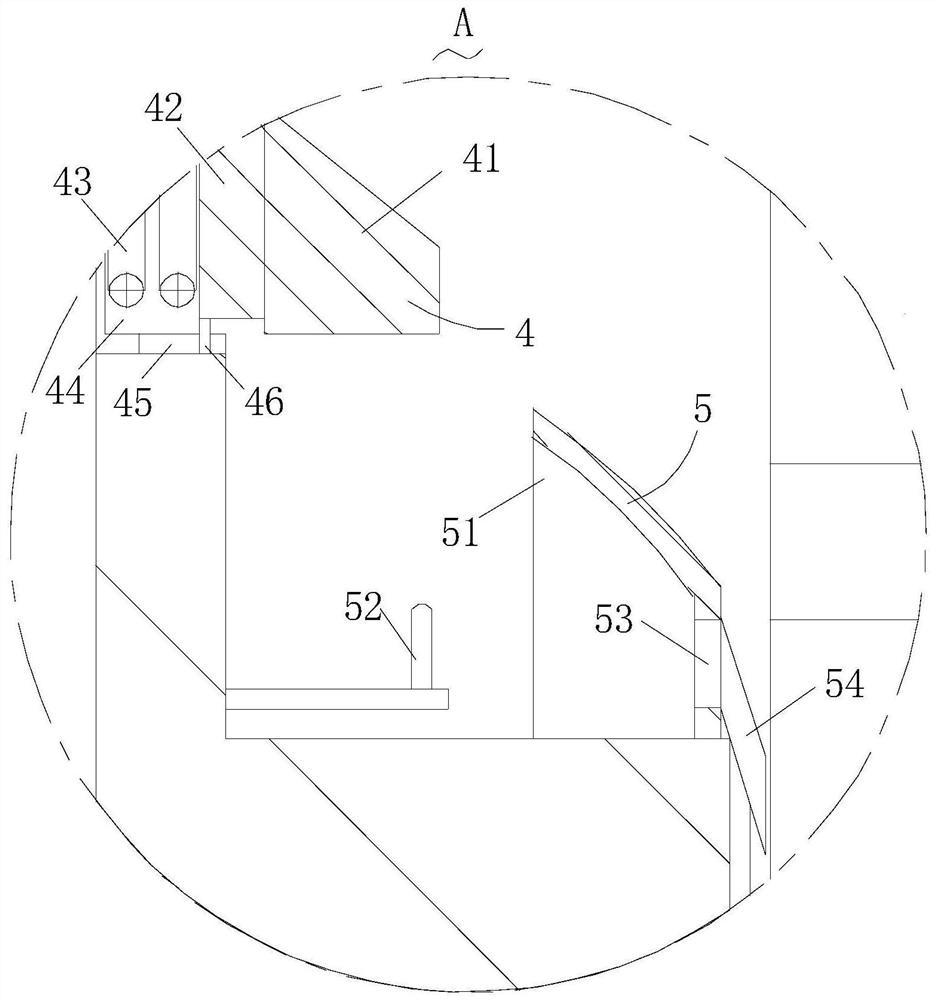
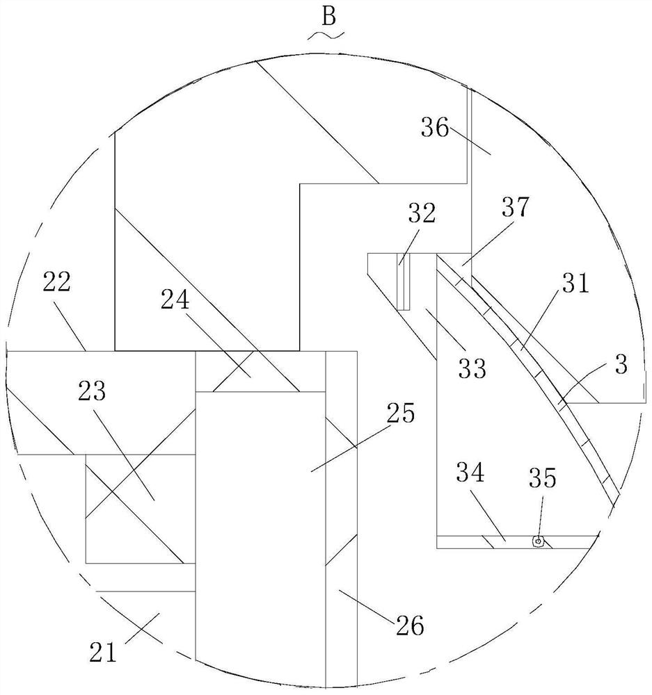
[0028] like Figure 1-Figure 6 As shown in the figure, a high-power output optical fiber coupler according to the present invention includes a casing 1, and a hot-melting mechanism 2 is arranged on the casing 1, and the hot-melting mechanism 2 is in contact with the splitting mechanism 3, so The splitting mechanism 3 is arranged inside the casing 1, and a limiting mechanism 4 is arranged inside the casing 1, and the limiting mechanism 4 is in contact with the splitting mechanism 3; the splitting mechanism 3 and the seal The sealing mechanism 5 is arranged inside the casing 1; a fastening mechanism 6 is installed on the casing 1, and the fastening mechanism 6 and the casing 1 are connected by threads, and the casing The body 1 is provided wit...


PUM


Abstract

The invention relates to the field of optical fiber couplers, in particular to a high-power output optical fiber coupler which comprises a shell, a hot melting mechanism is arranged on the shell, the hot melting mechanism abuts against a splitting mechanism, the splitting mechanism is arranged in the shell, and the hot melting mechanism abuts against the splitting mechanism. According to the optical fiber hot melting device, an optical fiber powder material in the hot melting mechanism can be detached through the arranged detaching mechanism, so that the optical fiber powder material enters the interior of the shell, when the hot melting mechanism carries out hot melting, the hot melting efficiency can be rapidly improved, and connection of optical fiber contact points after hot melting is firmer; the optical fiber surface and the shell are sealed more firmly, a good sealing effect is achieved, the surface of the optical fiber can be sealed through the arranged fastening mechanism, the fastening mechanism can further extrude the surface of the optical fiber while fastening the optical fiber, and therefore the fastening mechanism and the optical fiber are sealed.

Description

technical field [0001] The invention relates to the field of optical fiber couplers, in particular to a high-power output optical fiber coupler. Background technique [0002] When coupling the existing optical fiber couplers, it is generally necessary to use a hot-melt device to couple the fibers, and after the coupling is completed, the fibers are taken out from the hot-melt device. When connecting, it is difficult to align the end face of the optical fiber, and it is difficult to flatten the end of the optical fiber, so that the optical fiber needs to be flattened before the butt joint, which reduces the welding efficiency, and it is easy to make the joint after welding. When the fiber optic connector is not protected in water, the fiber optic connector is easily corroded, especially the corrosion phenomenon of the fiber optic connector located in seawater is more serious, which reduces the service life of the fiber. SUMMARY OF THE INVENTION [0003] In view of the prob...

Claims


Application Information

Patent Timeline
Patent Type & Authority Applications(China)
IPC IPC(8): G02B6/255
CPCG02B6/2551G02B6/2558G02B6/2553
Inventor 不公告发明人
Owner 鲍立新
Learn More