Process for producing flat heat excahnger tubes

A technology of heat exchange tubes and manufacturing methods, applied in the direction of heat exchange equipment, manufacturing tools, metal rolling, etc.

Inactive Publication Date: 2004-06-09
SHOWA DENKO KK
View PDF1 Cites 7 Cited by
  • Summary
  • Abstract
  • Description
  • Claims
  • Application Information

AI Technical Summary

Problems solved by technology

[0005] However, in the above-mentioned method of manufacturing flat heat exchange tubes, since it is necessary to sequentially pass the metal plate through a plurality of rolling mills, there is a problem of increasing the size of the entire manufacturing facility.

Method used


Image

  • Process for producing flat heat excahnger tubes
  • Process for producing flat heat excahnger tubes
  • Process for producing flat heat excahnger tubes

Examples


Embodiment 1

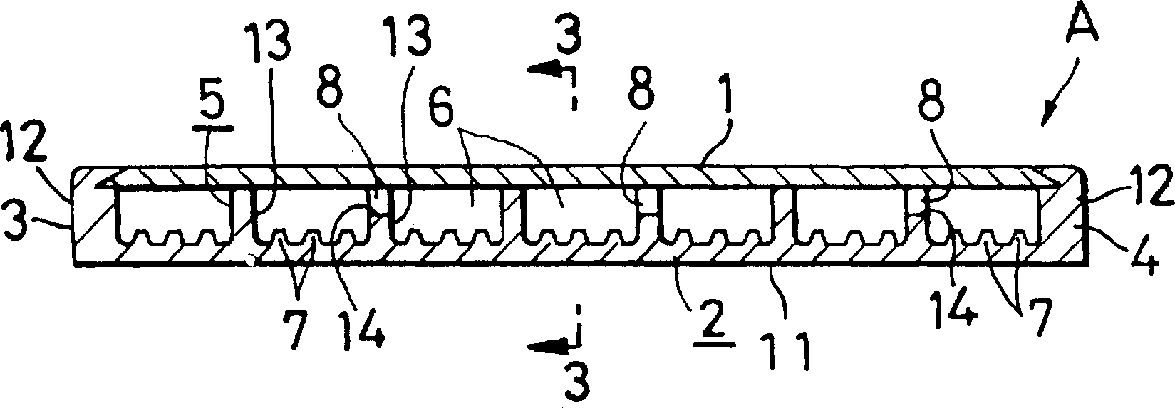
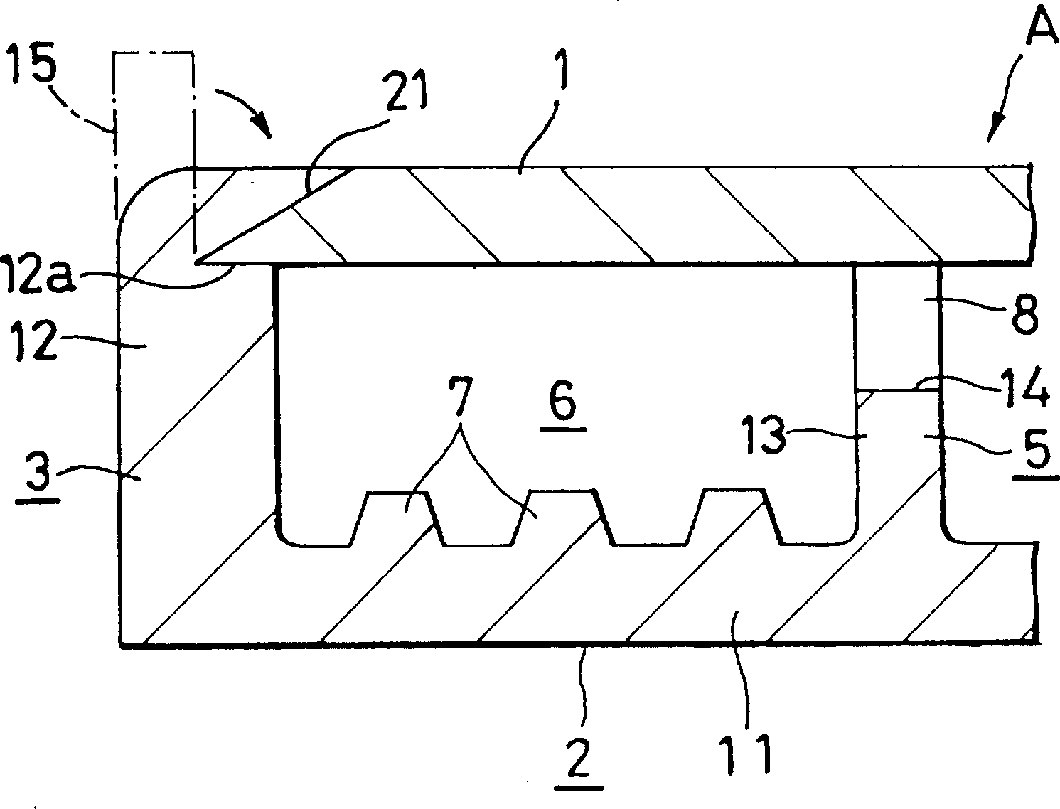
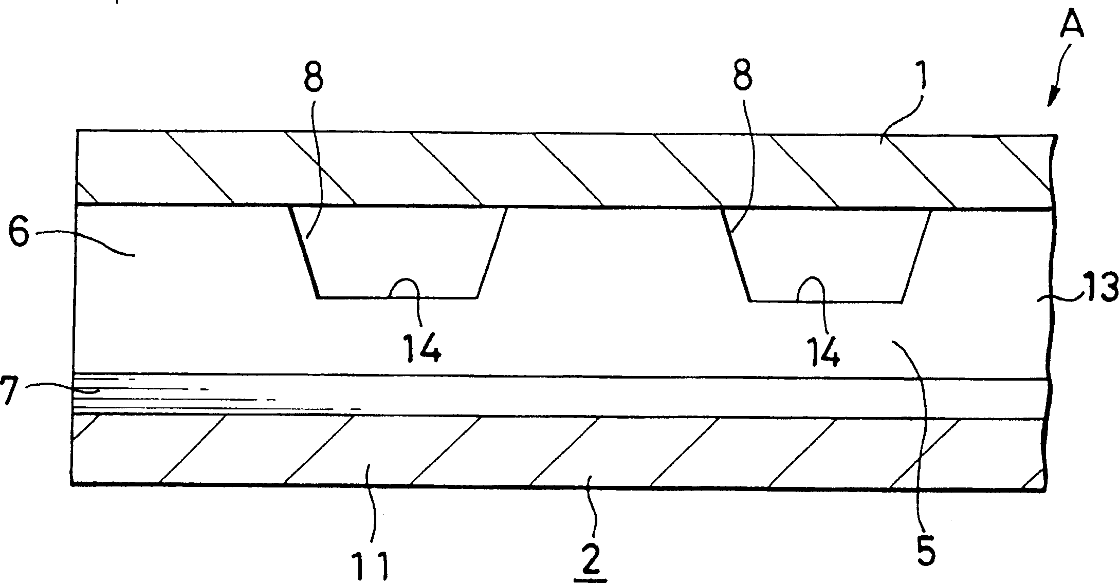
[0043] Figure 1 ~ Figure 1 1 indicates Example 1. Such as Figure 1 ~ Figure 3 As shown, the flat heat exchange tube (A) manufactured by the method of embodiment 1 is provided with: flat upper and lower walls (1), (2) brazed with cooling fins; straddling the upper and lower walls (1), ( 2) on the left and right side edges, the vertical left and right side walls (3), (4); between the left and right side walls (3), (4), across the upper and lower walls (1), (2) and A plurality of reinforced walls (5) extending along the length direction and arranged at a certain interval with each other; there are parallel refrigerant passages (6) inside. Low protrusions (7) for increasing the heat transfer area are integrally formed between mutually adjacent reinforcing walls (5) on the upper surface of the lower wall (2). A plurality of trapezoidal communication holes (8) are opened at the upper end of each reinforcing wall (5) to communicate the parallel refrigerant passages (6) with each...

Embodiment 2

[0060] 12 to 15 are diagrams showing Example 2. FIG.

[0061] The flat heat exchange tube (A) manufactured by the method of embodiment 2 1 ) as shown in Figure 12 and Figure 13, except that the left and right side walls (50), (51) form a double structure, the rest are all and

[0062] Embodiment 1 is the same.

[0063] Flat heat exchange tube (A 1 ) is composed of a lower structural member (60) and an upper structural member (70), but in the lower structural member (60), the left and right standing parts (61) have the same height and thickness as the protruding strip (5), and the flat part ( 11) The outward and upward slopes (62) are formed below the two side edges; and, in the upper structure (70), a hanging part (72) having the same thickness as the upright part (61) is formed on the two side edges. ), the lower ends of the two hanging parts (72) are folded and overlapped on the above-mentioned outwardly upward inclined surface (62), and its cross-section is made to be th...

Embodiment 3

[0070] Figure 16 ~ Figure 18 Figure showing Example 3.

[0071] The flat heat exchange tube (A) manufactured by the method of embodiment 3 2 ),Such as Figure 16 As shown, it is provided with: the flat upper and lower walls (86), (87) of the brazing fins; Side walls (85), (88); between the left and right side walls (85), (88), straddling the upper and lower walls (86), (87) and extending along the length direction and spaced apart from each other at a certain interval A plurality of reinforced walls (89); there are parallel refrigerant passages (74) inside. A plurality of hexagonal communication holes (90) for communicating the parallel refrigerant passages (74) are opened at the center of the height of each reinforcing wall (89).

[0072] Flat heat exchange tube (A 2 ) consists of 1 structural member (94). Such as Figure 17 As shown, the structural member (94) is provided with a central flat portion (92) forming the right side wall (88) in the center of the width, an...


PUM

PropertyMeasurementUnit
heightaaaaaaaaaa
thicknessaaaaaaaaaa
thicknessaaaaaaaaaa

Abstract

The invention relates to a manufacture method of flat heat exchange tube, which is provided with aluminum sheet materials rolled by rolling machine that is composed of central working roller and a plurality of working rollers, a parallel annular groove is formed on circumference surface of the central working roller, and then flat parts of lower wall are formed by the rolling machine, moreover the flat parts convexly form upright parts on left and right side walls and protrusion bars on reinforcing wall, the other aluminum plate is arranged on full protrusion bars to form an upper wall, moreover the aluminum plate is jointed with the two upright parts so as to make the two upright parts form left and right side walls, so that all protrusion bars are jointed with the upper wall to form the reinforcing wall.

Description

technical field [0001] The present invention relates to a method for manufacturing flat heat exchange tubes, and more particularly to a method for manufacturing flat heat exchange tubes used in heat exchangers such as condensers and evaporators in vehicle air conditioners. Background technique [0002] Recently, the condenser in the air-conditioning equipment for vehicles, such as the one disclosed in Japanese Patent Application Publication No. 45300 / 91, is provided with a pair of headers arranged in parallel to the left and right with a spaced distance from each other, and the two ends are respectively connected to the two headers. Parallel flat heat exchange tubes connected to each other, corrugated fins placed in the ventilation gap between adjacent heat exchange tubes and brazed to the two heat exchange tubes, inlet connected to the upper end of the left header Pipe, the outlet pipe connected to the lower end of the right header, the left isolation plate set inside the u...

Claims


Application Information

Patent Timeline
Patent Type & Authority Patents(China)
IPC IPC(8): B21D53/06B21B1/08B21B1/22B21B13/00B21C37/15B21C37/20B21D15/00B21H8/00F28D1/03F28F1/40F28F3/04
CPCB21H8/00B21C37/202B21C37/151F28F3/048B21B13/00B21B1/22F28D1/0316B21B1/0805B21B1/227
Inventor 齐藤好弘田村乔贝村哲穗积敏坂口雅司
Owner SHOWA DENKO KK
Why Eureka
Try Eureka