Velocity control with limited jolting

A speed control and speed technology, applied in general control system, digital control, program control, etc., can solve the problem that machine efficiency cannot be fully utilized, and achieve the effect of improving surface quality, accuracy, and contour accuracy

Inactive Publication Date: 2004-07-07
SIEMENS AG
View PDF2 Cites 2 Cited by
  • Summary
  • Abstract
  • Description
  • Claims
  • Application Information

AI Technical Summary

Problems solved by technology

But on the other hand, it causes the efficiency of the machine to not be fully utilized

Method used


Image

  • Velocity control with limited jolting
  • Velocity control with limited jolting
  • Velocity control with limited jolting

Examples


Embodiment Construction

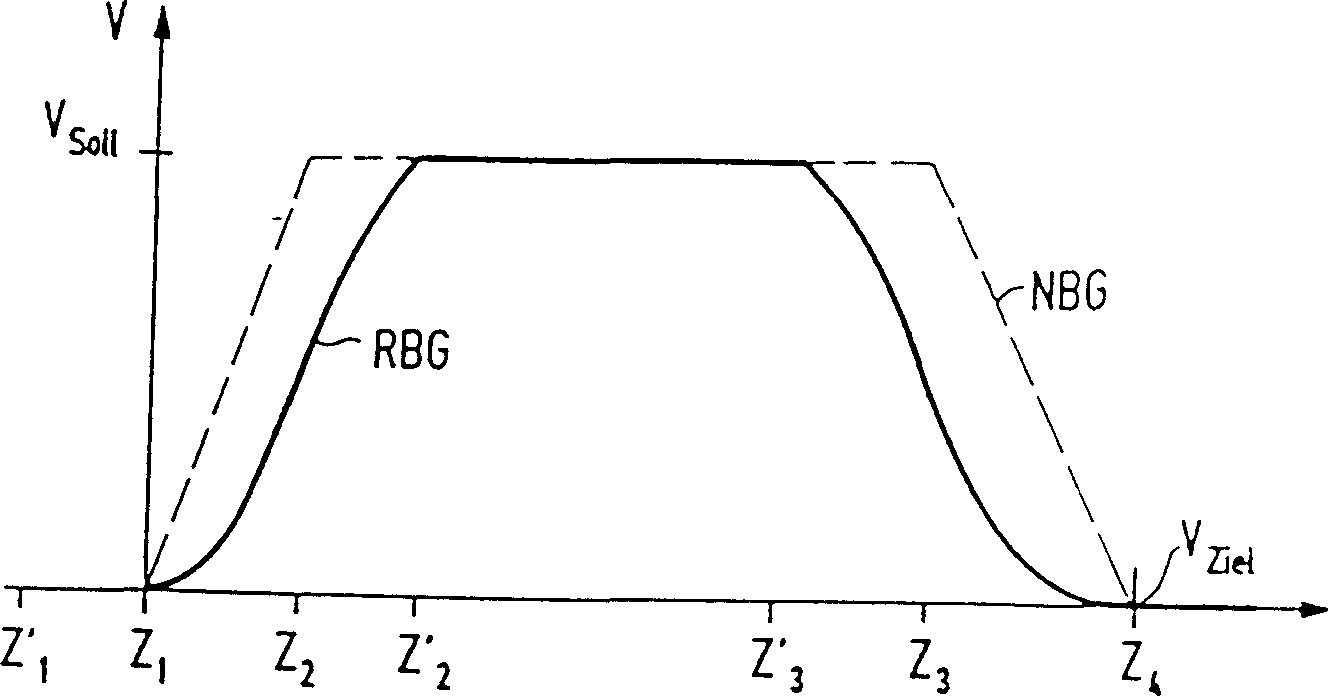
[0038] figure 1 Depicted in is a graph in which the variation of velocity V over time T is recorded. Each small segment on the abscissa represents an interpolation time scale. Two velocity values ​​are recorded on the ordinate. One is the current preset rated speed V soll , which at point Z 2 or Z' 2 time is reached. The second speed value is the target speed V ziel , which at a certain point in time Z 4 The top is braked to reach. at startup figure 1 The two curves in represent two different speed curves, the first speed curve is achieved without using the jerk-limited speed control according to the invention, which is the non-limited speed curve NBG in dashed form. It means that the velocity at time point Z 1 Starting from zero value and increasing linearly until time point Z 2 reaches the predetermined rated speed V soll until. at time point Z 2 and Z 3 Between, the unrestricted speed curve exhibits a constant value, namely the rated speed V soll , it is ste...


PUM


Abstract

The invention concerns a velocity control method for electric drives, in particular for machine tool control systems, wherein impact on the gear unit and machine caused by acceleration is restricted. To this end, control data are read in blocks, and predetermined nominal speeds (Vsoll) are approached as upper speed limits which are to be retained as far as possible, and local speed limits are approached in the form of target speeds (Vziel) at specific target points (Z4), looking ahead (Z'1, Z'3) within the framework of the look-ahead system with slight acceleration changes within the framework of the maximum permissible jolt. An acceleration limit which is independent of the speed can therefore be left at a constant high maximum value.

Description

technical field [0001] The invention relates to a method and a device for the speed control of an electric drive, in particular a machine tool or a robot. Background technique [0002] Modern drives, such as those for machine tools or robots, are characterized by high dynamics. The values ​​for the speed control which are predetermined by the industrial control on the setpoint side often contain sudden acceleration changes, which result in acceleration surges for the machine. If there is a so-called loosening effect on the drive connected to such a machine, that is to say, the play between the gears is adjusted during the working time, the drive is subjected to thrust loads. Due to the hysteresis profile of this slippery drive with looseness, the machine vibrates considerably. However, such vibrations are undesirable because, for example, they can cause poor surface quality when grinding workpieces, or dimensional degradation when laser cutting. For this reason, efforts a...

Claims


Application Information

Patent Timeline
Patent Type & Authority Patents(China)
IPC IPC(8): G05B19/416
CPCG05B2219/43058G05B2219/43034G05B2219/43065G05B2219/43041G05B19/416
Inventor 沃尔夫冈·斯佩斯威廉·韦斯特迈耶
Owner SIEMENS AG
Why Eureka
Try Eureka