
Filter plate of filter press

A filter press and filter plate technology, which is applied to the filter plate field of a filter press, can solve problems such as large workload, and achieve the effects of less maintenance, low manufacturing cost and less wear and tear.

Inactive Publication Date: 2004-08-04
OUTOKUMPU OY
View PDF3 Cites 2 Cited by
  • Summary
  • Abstract
  • Description
  • Claims
  • Application Information

AI Technical Summary

Problems solved by technology

[0007] The disadvantage of corner entry is that the filter cloth must be clamped to the filter plate in the entry area by means of a screw-in clamp
This results in a considerable amount of work when changing the filter cloth

Method used


Image

  • Filter plate of filter press
  • Filter plate of filter press
  • Filter plate of filter press

Examples


Embodiment Construction

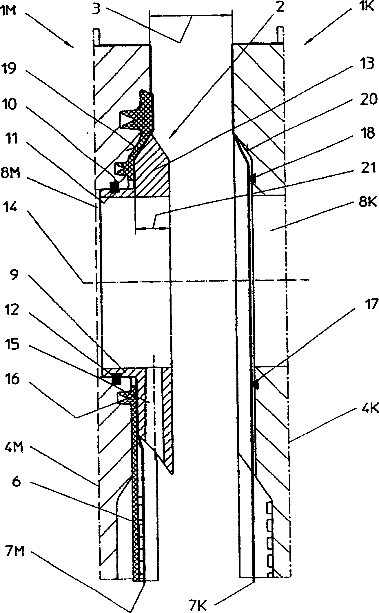
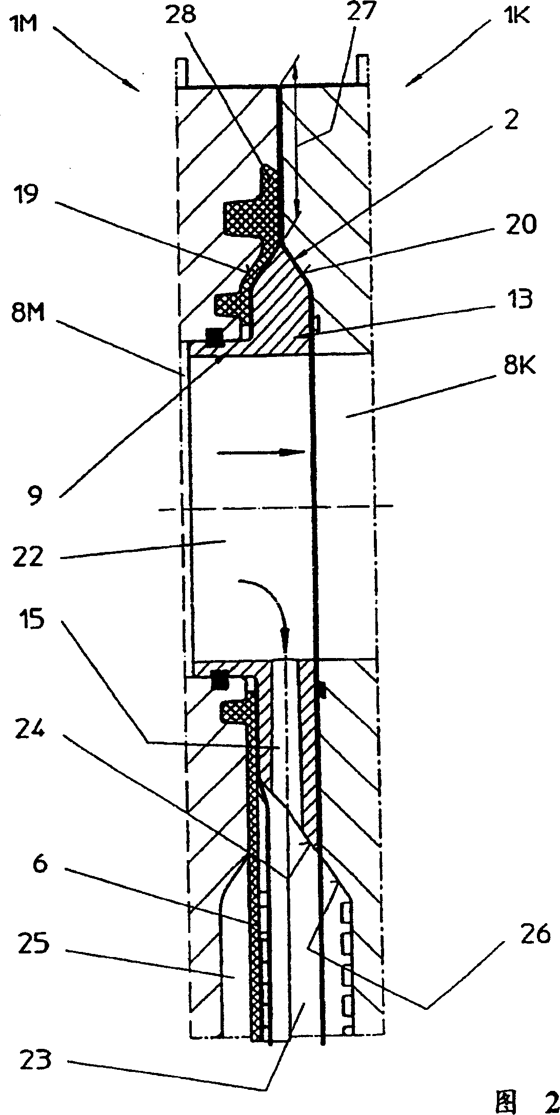
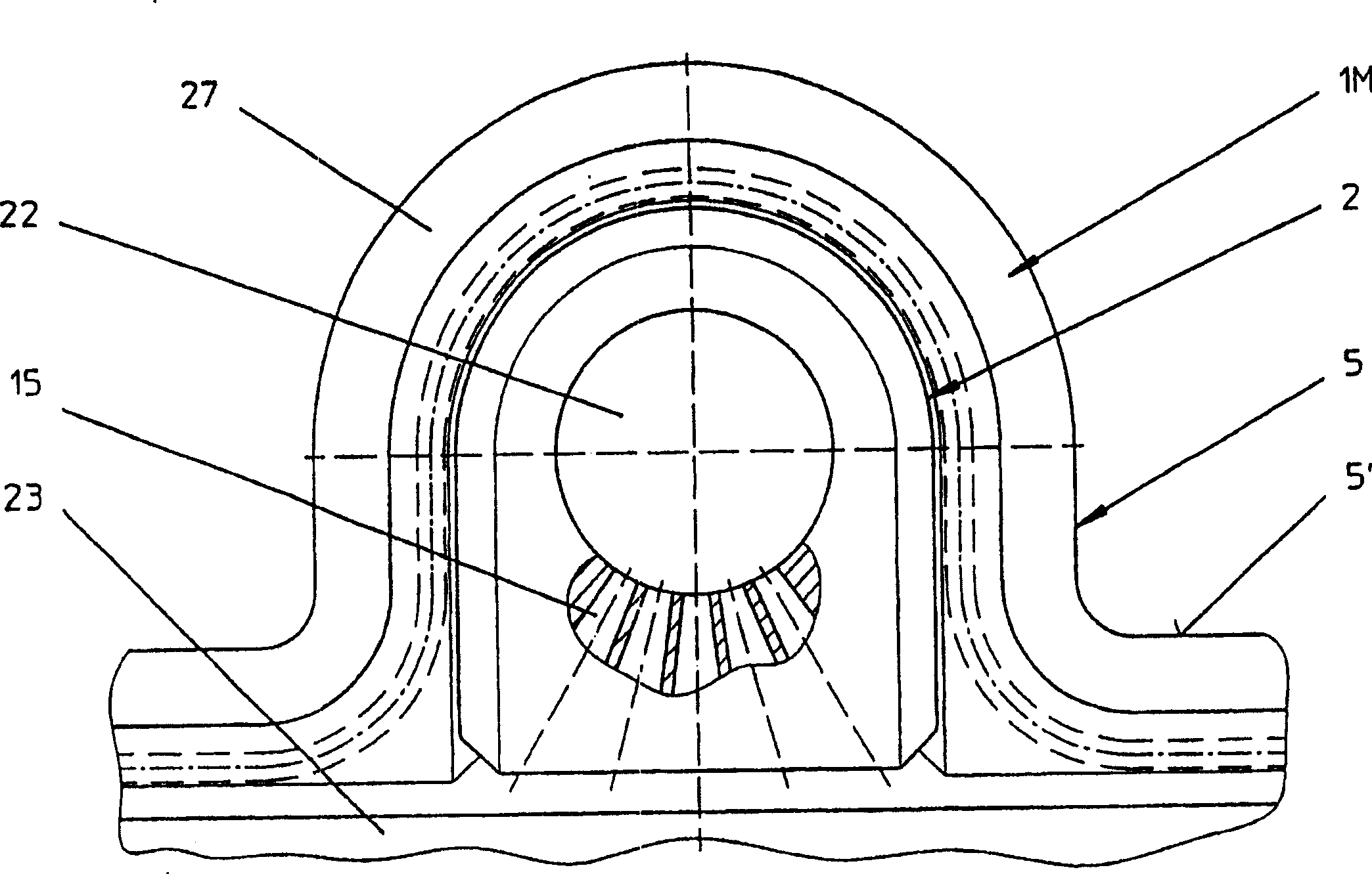
[0033] figure 1 The left half of the figure shows a longitudinal section through the right half of a filter plate used as a membrane plate 1M, but only its region in which the feed element 2 is inserted is shown. figure 1 The right half of FIG. 1 shows a chamber plate 1K separated from the membrane plate 1M by a slag discharge distance, but only its left half is shown. Both the membrane plate 1M and the chamber plate 1K are designed symmetrically with respect to their planes of symmetry 4M and 4K. For the sake of brevity, the halves of the sections of the two plates described which are opposite to each other and have the same structure are omitted in the figure. also, figure 1 The longitudinal sectional view of only shows the uppermost part of the filter plates 1M and 1K aligned in the vertical direction, that is, at the filter plate edge 5' (which becomes the upward boundary of the substantially rectangular filter plate filter area in the filter plate 1M ) above the Annex ...


PUM


Abstract

The invention relates to a filter press (1) for filtering suspensions that comprises a plurality of filter plates (1M, 1K) that can be displaced in parallel with respect to one another. In a filtering position, said filter plates can be compressed to a package that comprises a filter chamber (23) between respective two filter plates (1M, 1K), said chamber being provided with at least one filter cloth (7M, 7K). In a discharge position, adjoining filter plates (1M, 1K) can be moved apart by a discharge distance (3) so that the filter cake adhering to the filter cloth (7K) can be discharged. Every filter chamber (3) is correlated with at least one filling element (2) for feeding the suspension to the filter chamber (23). The aim of the invention is to prevent leakages in the zone of the peripheral sealing edge, to guarantee an unimpaired filter capacity during feeding and to facilitate operation of the filter press without an external supply line and outgoing connection lines. To this end, the filling element (2) is disposed on a joining piece (5) that extends outside a plate level and within a sealing edge (27) on the periphery of the filter plates (1M, 1K) and that can be linked with a filter plate (1M). In the filtering position, the filling elements (2) form a suspension supply channel (22) that extends through the filter plate package and are sealingly wedged between adjoining filter plates (1M, 1K).

Description

technical field [0001] The invention relates to a filter plate for a filter press used to filter suspensions, wherein a plurality of filter plates arranged in parallel to each other and relatively movable can be compressed into a filter plate group at the filtering position, and the filter plate group is used for each filter plate group. There is a filter cavity with at least one filter cloth set between the two filter plates, wherein the filter plates can be separated from each other by a slag discharge distance when they are in the slag discharge position, wherein each filter cavity is provided with at least one suspension Feed parts to the filter cavity. Background technique [0002] A filter press with such a filter plate is known from European patent specification EP-0540705 B1. The feed element there is in each case a rod-shaped tubular body which is seated sealingly in an edge-side groove-shaped recess running in the direction of the sealing edge on the edge region. ...

Claims


Application Information

Patent Timeline
Patent Type & Authority Patents(China)
IPC IPC(8): B01D25/12B01D25/168B01D25/21B01D25/30
CPCB01D25/215B01D25/30
Inventor 卡尔·格拉芬赫曼-约瑟夫·斯波尔根
Owner OUTOKUMPU OY
Learn More