Color cathode ray tube
A cathode ray tube and color technology, applied in the direction of cathode ray tubes/electron beam tubes, discharge tubes, electrical components, etc., can solve the problems that the positional relationship is not disclosed, the added value is reduced, etc., to ensure mass production rate and increase the effective diameter , Improve the effect of magnetic coupling
- Summary
- Abstract
- Description
- Claims
- Application Information
AI Technical Summary
Problems solved by technology
Method used
Image

Examples
no. 1 example
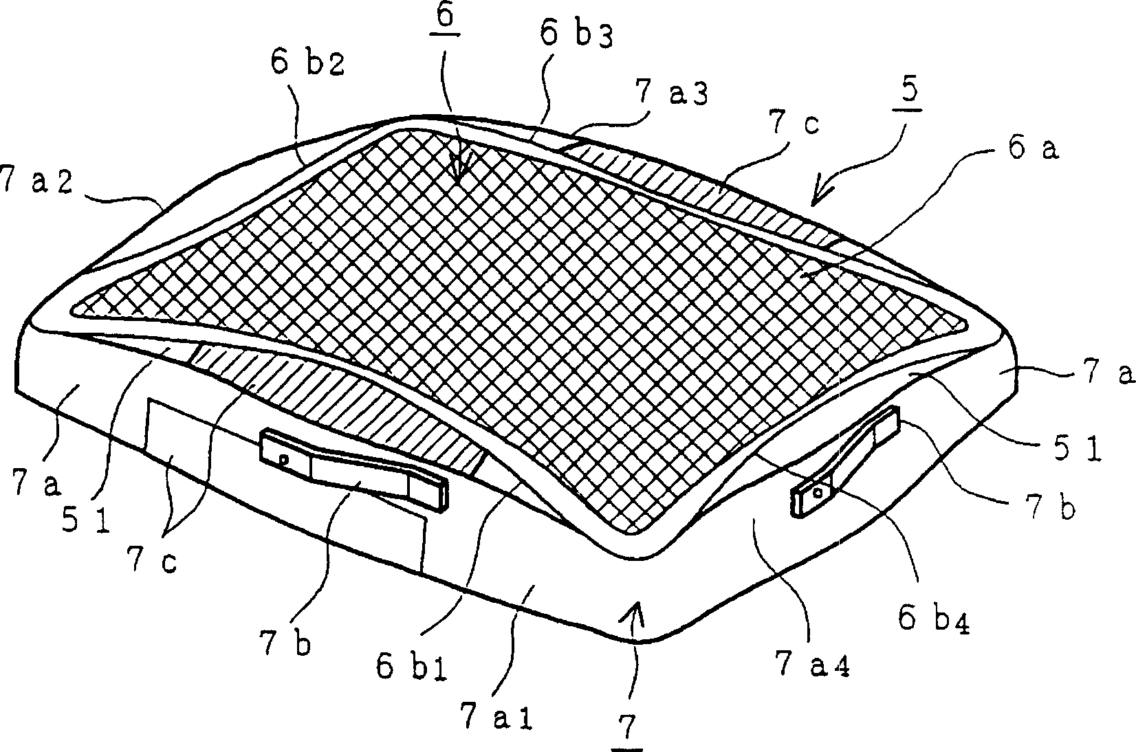
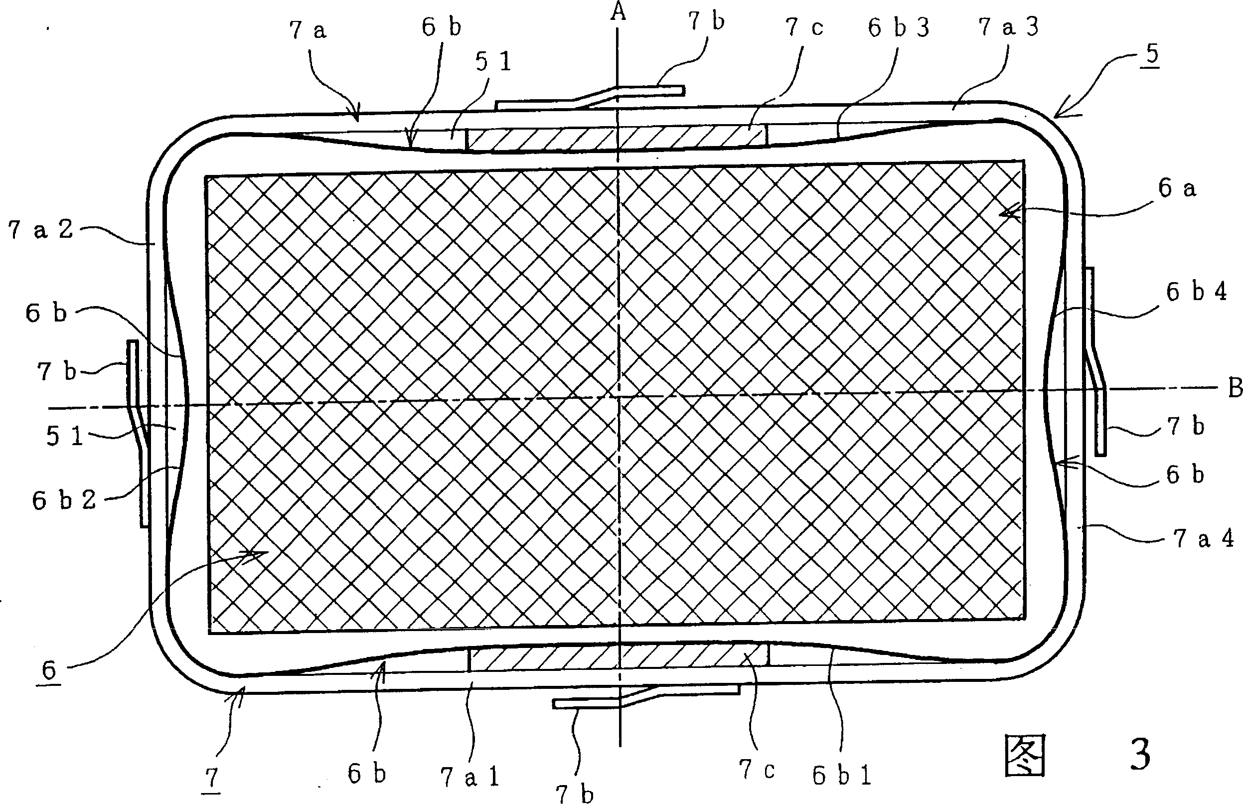
[0062] figure 2 is used for figure 1 A perspective view of an example of a shadow mask 5 in a color cathode ray tube, Fig. 3 is figure 2 A top view of the shadow mask assembly 5 in .
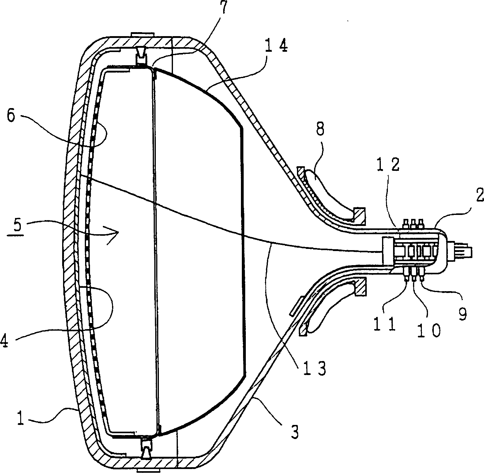
[0063] exist figure 2 And in Fig. 3, reference numeral 6a represents the curved surface of shadow mask 6, 6b represents the skirt of shadow mask assembly 6, 6b 1 、6b 2 、6b 3 and 6b 4 Represents the four sides of the skirt 6b, 7a represents a side wall of the shadow mask frame 7, 7a 1 、7a 2 、7a 3 , and 7a 4 7b represents the four sides of the wall 7a, 7b represents the reed, and 7c represents the protrusion on the shadow mask frame 7. exist figure 2 and Figure 3, with figure 1 Other identical elements in have the same label. Axis A is an axis that passes through the center of the mask assembly and is approximately parallel to the smaller sides of the assembly; axis B is an axis that passes through the center of the mask assembly and is approximately parallel to the longer sides...
no. 2 example
[0092] Figure 8 is a top view of a shadow mask assembly of a second embodiment of the present invention. Reference numeral RF1 represents the radius of curvature of the longer side inside the sidewall, RM1 represents the radius of curvature of the edge of the shadow mask, RF2 represents the radius of curvature of the smaller side inside the sidewall, and RM2 represents the radius of curvature of the smaller side of the edge of the shadow mask. Other parts that are the same as those in Fig. 3 are designated with the same reference numerals.
[0093] In the case of the present embodiment, the value of the radius of curvature RF1 or RF2 on the inner side of the side wall on one side of the mask frame 7 is set to be smaller than the radius of curvature RM1 or RM2. According to the present embodiment, the gap at the central part of the joint area between the four-sided skirt of the shadow mask and the shadow mask frame and the corresponding four-sided side walls is relatively inc...
no. 3 example
[0098] Figure 9 is a top view of a shadow mask assembly according to a third embodiment of the present invention. The same components as in Fig. 3 are given the same reference numerals. In the case of this embodiment, the shadow mask 6 is made of Invar. Since Invar is hard, the skirt 6b is made shorter.
[0099] Figure 10A shown along Figure 9 In the A-A line Figure 9 Sectional view of the longer side of the medium, Figure 10B shown along Figure 9 of the B-B line in Figure 9 Cutaway view of the shorter side of the medium, Figure 10C shown along Figure 9 The C-C line in Figure 9 Cutaway view of the corner in .
[0100] The feature of this embodiment is that the skirt 6b of the shadow mask is closer to the side wall of the shadow mask frame than the protrusion 7c formed at the nearest edge between the flange 71a and the side wall 7a, that is, The skirt 6b is closer to the phosphor screen than the protrusion 7c formed at the nearest edge. Therefore, even if...
PUM
 Abstract
Description
Claims
Application Information
 - R&D Engineer
- R&D Manager
- IP Professional
- Industry Leading Data Capabilities
- Powerful AI technology
- Patent DNA Extraction
Browse by: Latest US Patents, China's latest patents, Technical Efficacy Thesaurus, Application Domain, Technology Topic.
© 2024 PatSnap. All rights reserved.Legal|Privacy policy|Modern Slavery Act Transparency Statement|Sitemap