Deflectnig system of Braun tube

A technology of deflection yoke and convergence system, applied in the field of deflection yoke, which can solve the problems of increased manufacturing cost, screen misconvergence, increased production cost, etc.

Inactive Publication Date: 2004-09-29
MERIDIAN SOLAR & DISPLAY
View PDF0 Cites 0 Cited by
  • Summary
  • Abstract
  • Description
  • Claims
  • Application Information

AI Technical Summary

Problems solved by technology

[0031] However, since the prior art Braun tube installs the auxiliary 4-pole convergence system 40 at the ferrite core 34, as Figure 9 The magnetic field of the horizontal deflection coil 31 shown generates an induced electromotive force at the auxiliary coil 41 of the ferrite core 34, and the induced electromotive force interferes with the direction of the magnetic field generated by the auxiliary coil 41 to the horizontal deflection magnetic field, thereby causing misconvergence on the screen
[0032] In order to prevent misconvergence, as shown in Figure 4, it is necessary to install an induced current prevention circuit at the auxiliary 4-pole convergence system 40 to synchronize the horizontal compensation coil 51 and the vertical compensation coil 53, which makes the use of this Braun tube Product manufacturing costs increase
[0033] Also, in the conventional Braun tube, the auxiliary 4-pole converging system 40 is manufactured by winding the auxiliary coil 41 on the ferrite core 34 by using an additional winding machine, which causes the winding of the auxiliary coil 41 to take much time. question
[0034] Furthermore, when the auxiliary 4-pole convergence system 40 is combined with the ferrite core 34, misconvergence on the screen varies due to combination dispersion, resulting in poor productivity and increased production cost

Method used


Image

  • Deflectnig system of Braun tube
  • Deflectnig system of Braun tube
  • Deflectnig system of Braun tube

Examples


Embodiment Construction

[0073] Preferred embodiments of the present invention will be described in detail below with reference to the examples shown in the accompanying drawings.

[0074] Several embodiments of the deflection yoke of the Braun tube are possible according to the invention, of which only the most preferred embodiments are described.

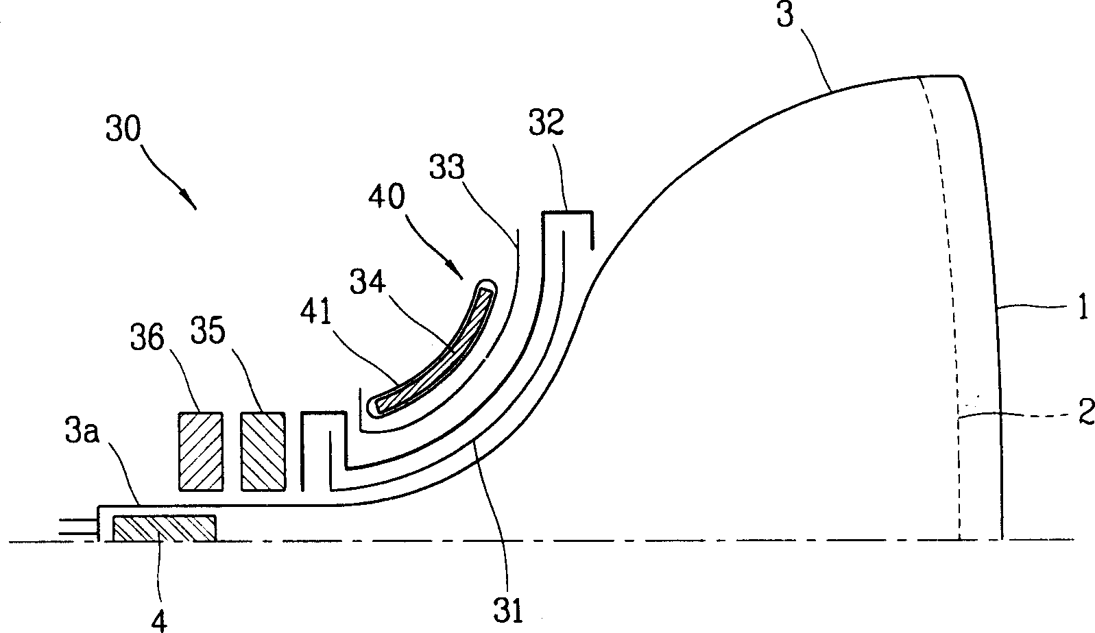
[0075] Figure 10 is a schematic diagram of a Braun tube with a deflection yoke according to a first embodiment of the invention.

[0076] The Braun tube includes: an electron gun 105 for emitting three electron beams from the rear side of a cone 110; a phosphor screen 101 on which the electron beams impinge to generate light; a shadow mask 102 for discriminating the three electron beams; and a deflection yoke 130 for deflecting the electron beams to a predetermined point on the screen 101.

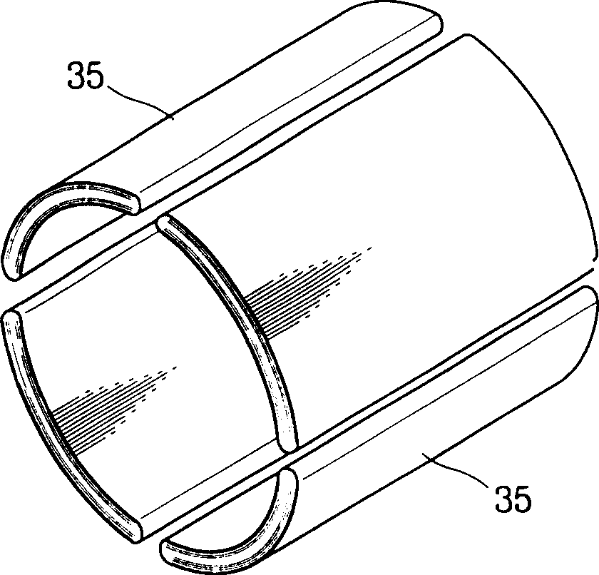
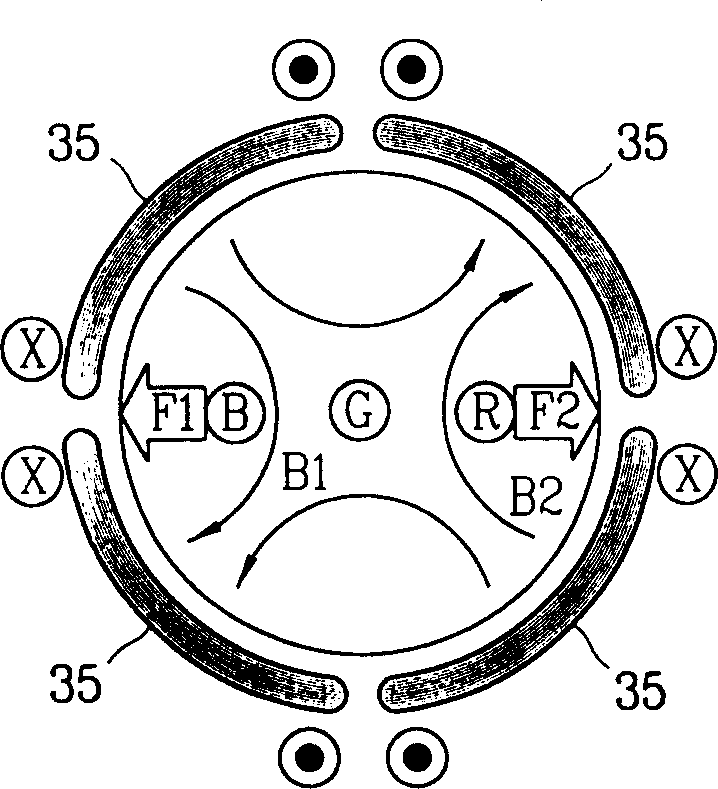
[0077] The deflection yoke 130 controls positions where the R, G and B electron beams emitted from the electron gun 105 impinge on the screen 101 to display a desi...


PUM


Abstract

A deflection yoke for a Braun tube includes a primary 4-pole convergence yoke adapted to be positioned at a neck portion of a funnel of a Braun tube and a secondary 4-pole convergence yoke positioned in the vicinity of the funnel where horizontal and vertical deflection coils and a ferrite core are installed, for correcting a misconvergence generated due to the primary 4-pole convergence yoke, wherein at least one of the vertical and the horizontal deflection coils is wound at a first holder, and the secondary 4-pole convergence yoke is installed as an auxiliary coil wound on at least one side of the inner side or the outer side of the first holder.

Description

technical field [0001] The present invention relates to deflection yokes for Braun tubes, in particular to an improved deflection yoke for Braun tubes with an auxiliary 4-pole focusing system for correcting misconvergence caused by the main 4-pole focusing system, and also to the Manufacturing method of deflection yoke. Background technique [0002] figure 1 A partial sectional view showing a common Braun tube, which includes: an electron gun 4 for emitting three electron beams from the rear side of a cone 3; a screen 1 on which the electron beams impinge to generate light; a shadow mask 2 for Discriminating three electron beams; and a deflection yoke 30 for deflecting the electron beams to a predetermined point on the screen 1. [0003] Braun tubes are used to accept an electrical signal from an external source of the image, change it into an optical signal, and display it as an image with spatial position and functional content (color, brightness) on the screen 1 . [0...

Claims


Application Information

Patent Timeline
Patent Type & Authority Patents(China)
IPC IPC(8): H01J29/70
CPCH01J29/703
Inventor 赵相俊李锡文
Owner MERIDIAN SOLAR & DISPLAY
Why Eureka
Try Eureka