
Temperature compensation Fabry-perot optical fiber strain sensor specially for concrete

A strain sensor and concrete technology, applied in the direction of optical devices, instruments, scientific instruments, etc., can solve the problems of low precision, large error, inaccurate sensor strain data, etc., and achieve the effect of ensuring accuracy

Inactive Publication Date: 2004-10-06
CHONGQING YA PAI BRIDGE ENG QUALITY TESTING CO LTD
View PDF0 Cites 0 Cited by
  • Summary
  • Abstract
  • Description
  • Claims
  • Application Information

AI Technical Summary

Problems solved by technology

However, the existing optical fiber strain sensor cannot complete this task alone, and an additional temperature sensor needs to be installed as a temperature compensation sensor to record the temperature at the same time, calculate the temperature deformation of the concrete, and remove the temperature strain from the comprehensive strain
That is to say, two sensors must be installed at one measuring point, which will double the number of sensors in the monitoring system, bring about a series of problems in sensor network design, wiring, protection, etc., and greatly increase the cost of the measurement system
[0004] 2. Since concrete is an anisotropic non-uniform material, its coefficient of thermal expansion is different with different formulations. Therefore, even if the temperature sensor is used to obtain the temperature parameters, the calculated temperature strain is not accurate and has a large error. Therefore, the above-mentioned temperature compensation The accuracy of the method is not high
But in this way, the strain of the concrete structure must first be transmitted to the metal member, and then transmitted to the optical fiber Fab strain sensor through the adhesive, so there are at least several problems: First, the optical fiber strain sensor does not directly measure the concrete structure. Strain, but to measure the strain after two transmissions and conversions of metal components and adhesives; second, the thickness and stiffness of adhesives will greatly affect the accuracy of the above-mentioned strain transfer, which in turn will affect the accuracy of the sensor. At the same time, the life of the adhesive will affect the life of the sensor; the third is that the rigidity of the metal component is greater than that of the concrete structure, so that local stress concentration is formed in the concrete around the metal component, resulting in inaccurate strain data measured by the sensor

Method used


Image

  • Temperature compensation Fabry-perot optical fiber strain sensor specially for concrete
  • Temperature compensation Fabry-perot optical fiber strain sensor specially for concrete

Examples


Embodiment Construction

[0016] The present invention will be further elaborated below in conjunction with the embodiment of accompanying drawing:

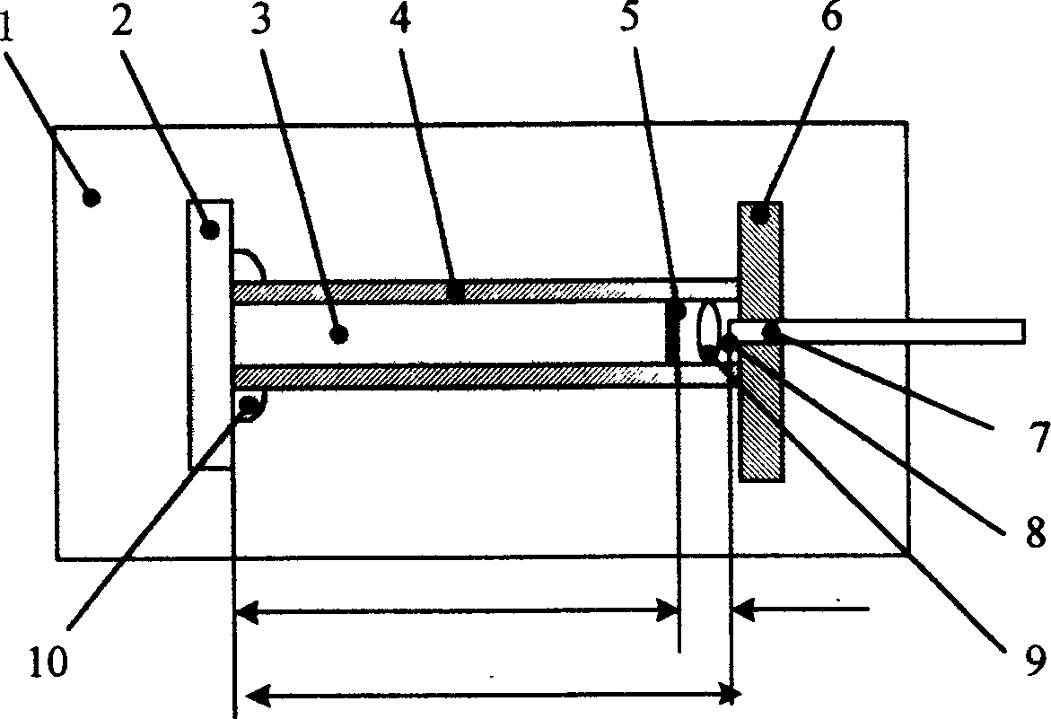
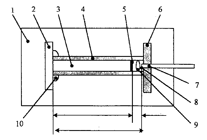
[0017] See attached figure 1 , The temperature self-compensating fiber optic Fab strain sensor is dumbbell-shaped in appearance and consists of three parts: a compensation column 3, a rigid protective shell 4 and an optical fiber 7. Wherein, the optical fiber 7 is installed on a rigid disc 6 and welded together with the rigid protective shell 4 . The compensation column 3 is placed in the rigid protective shell 4, the tail end 2 is fixed, and the front end can be freely expanded and contracted. The front end 5 coated with an optical reflective film is close to the end face of the optical fiber 7 also coated with an optical reflective film to form a F-Per interference cavity 9; The diameter of the tail end 2 of the reflective column 3 is larger than that of the end rigid protective shell 4 , which is exposed and bonded with the rigid protective shell 4 th...


PUM


Abstract

The dumbbell-shaped Fabry-Perot fiber strain sensor includes optical fiber, compensating column and rigid outer casing. The reflecting end of the compensating column is opposite to the end of the optical fiber to form Fabry-Perot interference cavity and the compensating column has front end capable of extending freey inside the protecting casing the tail end fixed. The compensating column is made of material with thermal expansion coefficient the same as or near to that of concrete where the sensor is embedded. The sensor has the advantages of automatic compensation of temperature deformation, strong signal and accurate measured data.

Description

technical field [0001] The invention belongs to the intersection field between the field of optical fiber sensor and the field of state monitoring of civil infrastructure, and in particular relates to an optical fiber strain sensor capable of self-compensating the temperature deformation of concrete. technical background [0002] Large bridges, dams, highways, tunnels, high-rise buildings, etc. need to be constantly monitored during the construction process and use after construction to ensure their construction quality and operational safety. Because these facilities are basically concrete structures, and the anisotropy and non-uniformity of concrete materials make it very difficult to monitor the stress / strain inside these structures, so the optical fiber strain sensor is vigorously developed internationally to solve the internal stress / strain of concrete. monitoring problem. The non-intrinsic Fabry-Perot Interferometer is the most widely used one, b...

Claims


Application Information

Patent Timeline
Patent Type & Authority Patents(China)
IPC IPC(8): G01B9/02G01N3/00G01N21/45G01N33/38
Inventor 朱永陈伟民陈小强
Owner CHONGQING YA PAI BRIDGE ENG QUALITY TESTING CO LTD
Learn More