Supercharge Your Innovation With Domain-Expert AI Agents!

Control method for test module of CCD

A charge-coupled element, detection module technology, used in electrical components, TV, TV system scanning details, etc.

Inactive Publication Date: 2004-12-01
AVISION
View PDF1 Cites 0 Cited by
  • Summary
  • Abstract
  • Description
  • Claims
  • Application Information

AI Technical Summary

Problems solved by technology

Although only the image signals corresponding to the signal charges S1, S3...S10799 or signal charges S2, S4...S10800 are selected when scanning with a resolution of 600dpi, the time required for the shift output is the same as that for the The scan with a resolution of 12000dpi is the same
So even though it's a low-res scan, it still takes the same amount of time to complete the scan as a high-res scan

Method used


Image

  • Control method for test module of CCD
  • Control method for test module of CCD
  • Control method for test module of CCD

Examples


Embodiment Construction

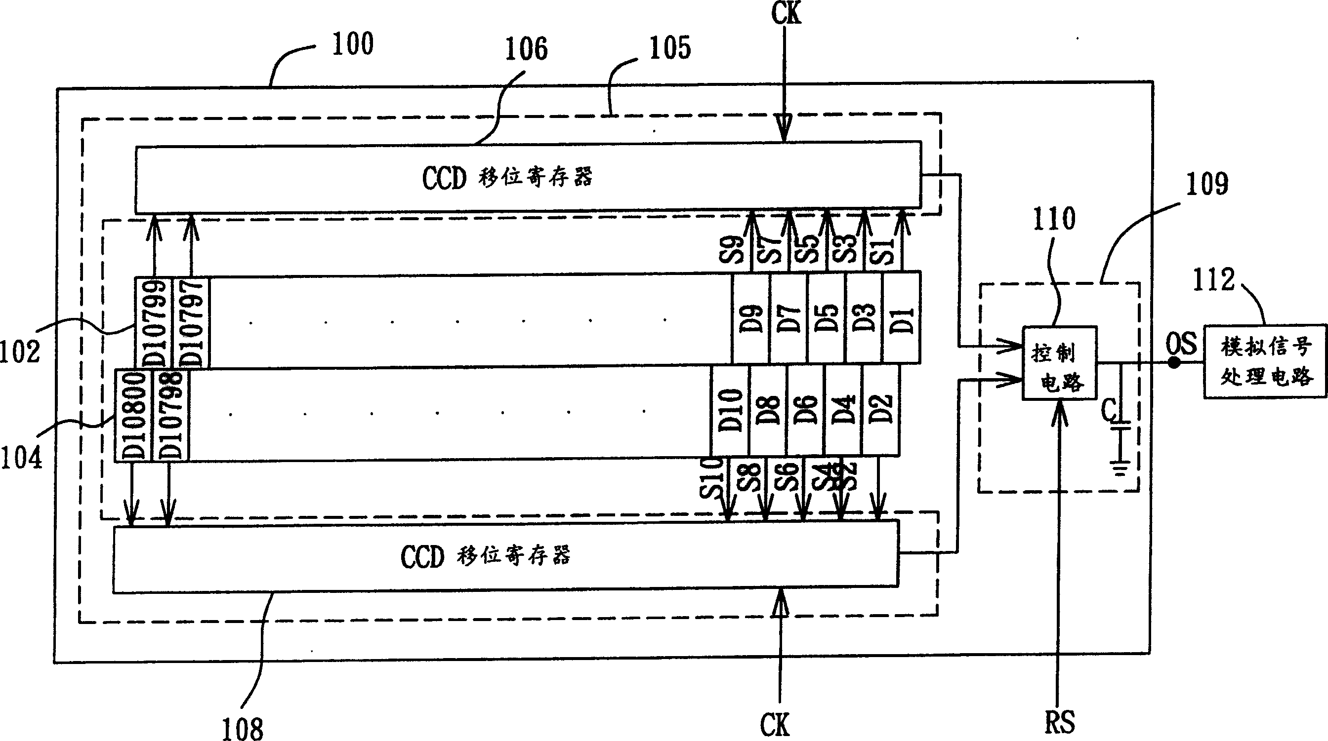
[0025] In the control method of a charge-coupled device (CCD) detector of the present invention, the CCD detection module includes a plurality of photodetectors, at least one CCD shift register, and at least one output capacitor. These photodetectors are divided into two groups, including an odd-numbered photodetector group and an even-numbered photodetector group. These photodetectors are used to convert the detected light signals into signal charges, and then output them in parallel. to the CCD shift register. The control method of the present invention includes: first, enter step (a), and expose the odd-numbered photodetector group and the even-numbered photodetector group, and the odd-numbered signal charge obtained after the odd-numbered photodetector group and the even-numbered photodetector group Even signal charges will be stored in the aforementioned CCD shift registers respectively.

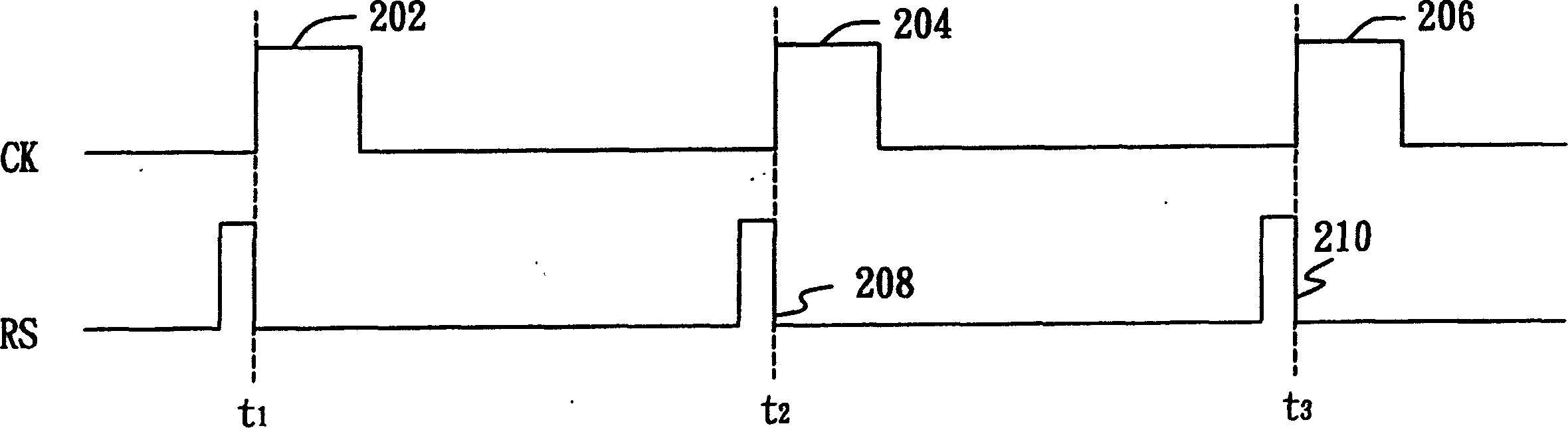
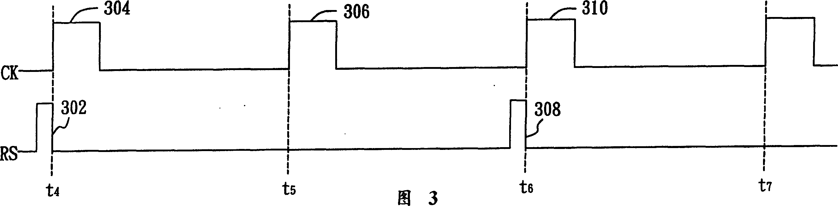
[0026] Next, enter step (b), sequentially shift and output the odd-numbered signal...


PUM


Abstract

A control method for detecting module of charge coupled device (CCD) divides the photodetector within CCD detecting module into the first photodector group and the second photodector group and it works as follows: making exposure to the abovesaid two groups, shifting and outputting the first signal charge and the second signal charge the CCD shift register to a charge receiving unit in sequence, picking the image signal corresponding to the first signal charge and making exposure to the abovesaid two groups once more, and finally shifting and outputting the first and the second signal charges the CCD shift register to the charge receiving unit in sequence and picking the image signal corresponding to the second signal charge.

Description

technical field [0001] The invention relates to a control method of a charge-coupled element detection module, in particular to a control method of a charge-coupled element detection module used in a scanner. Background technique [0002] In the image scanner, the charge-coupled device (CCD) detection module is used to capture the optical signal corresponding to the image to be scanned, convert it into an image signal and send it to the lower analog signal processing circuit for further image signal processing . In order to achieve high-resolution image scanning, a high-resolution image detector using a staggered detection structure has been disclosed in US Pat. No. 4,438,457. The CCD detection module using this interleaved detection structure has been widely used in the industry. [0003] refer to figure 1 , which is a schematic diagram of a conventional interleaved CCD detection module 100 using an interleaved detection structure. figure 1 The CCD detection module 100 ...

Claims


Application Information

Patent Timeline
IPC IPC(8): H04N1/03H04N1/195
Inventor 陈琰成
Owner AVISION
Features
  • R&D
  • Intellectual Property
  • Life Sciences
  • Materials
  • Tech Scout
  • Unparalleled Data Quality
  • Higher Quality Content
  • 60% Fewer Hallucinations
Learn More