
V-shaped belt speed transmission

A transmission and belt-type technology, applied in the direction of belts/chains/gears, transmission parts, connecting components, etc., can solve the problems of not getting enough supporting area, hindering the introduction of external air, and not being able to obtain machining accuracy, so as to improve the processability and productivity, alleviating pressure unevenness, and preventing dust and water from entering

Inactive Publication Date: 2005-01-05
HONDA MOTOR CO LTD
View PDF1 Cites 0 Cited by
  • Summary
  • Abstract
  • Description
  • Claims
  • Application Information

AI Technical Summary

Problems solved by technology

[0008] In such a case where outside air is introduced into the power transmission cover 08, even if a filter or the like is installed in the introduction part to remove dust, fine dust and the like will also enter the belt cover 08, and water will also enter at the same time, and the dust and Moisture enters the threaded part of the shaft end external thread 01a of the crankshaft 01 and the nut 05 to cause corrosion, so the threaded part must be tightened with more than necessary strength, making it difficult to loosen the nut 05 during maintenance
[0009] Moreover, the variable force of the belt reaction force of the fixed pulley half body 03 relative to the posture of the crankshaft 01 increases the force acting on the nut 05 screwed to the outer shaft end of the fixed pulley half body 03. Therefore, in order to obtain sufficient strength, the external thread 01a The body of the threaded part with the nut 05 needs to be enlarged, which may hinder the introduction of external air
[0010] In the case of an integrated crankshaft in which the crankshaft 01 and the crankpin are integrally formed, when the crankshaft 01 with a long dimension is processed, it is necessary to provide a centering hole 01b for supporting the two shaft ends on the external thread 01a, such as Image 6 The centering hole 01b provided on the external thread 01a shown must be limited below the thread size, and a sufficient supporting area cannot be obtained, so good processing accuracy cannot be obtained, and the processability is poor

Method used


Image

  • V-shaped belt speed transmission
  • V-shaped belt speed transmission
  • V-shaped belt speed transmission

Examples


Embodiment Construction

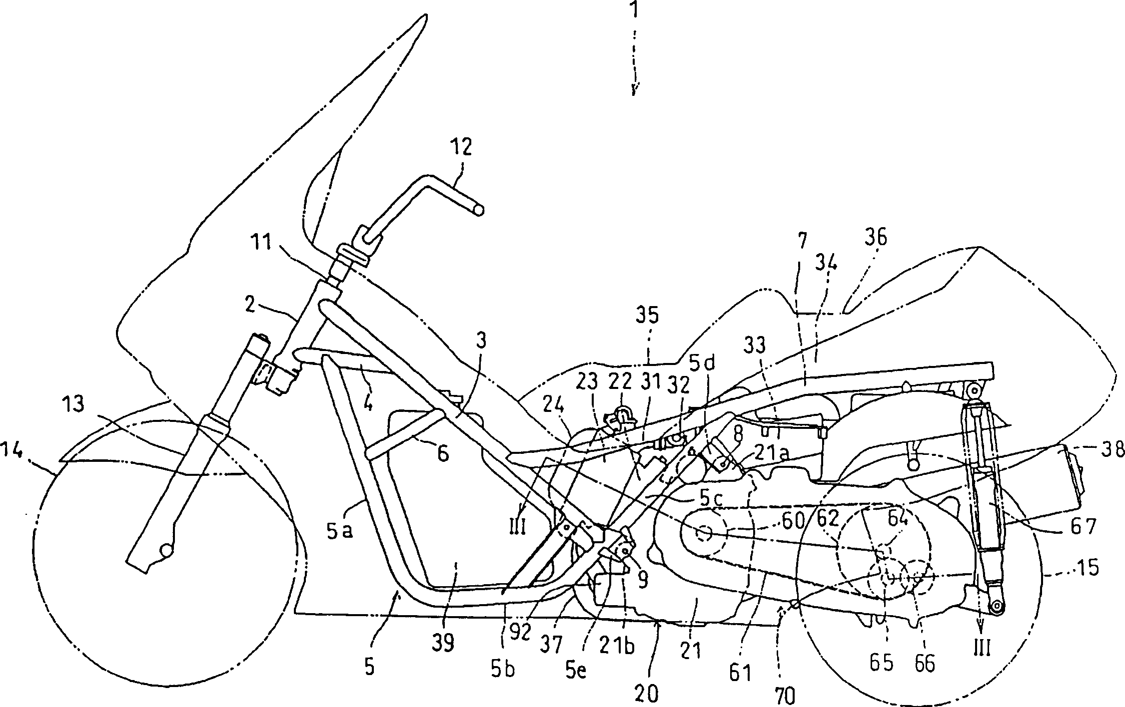
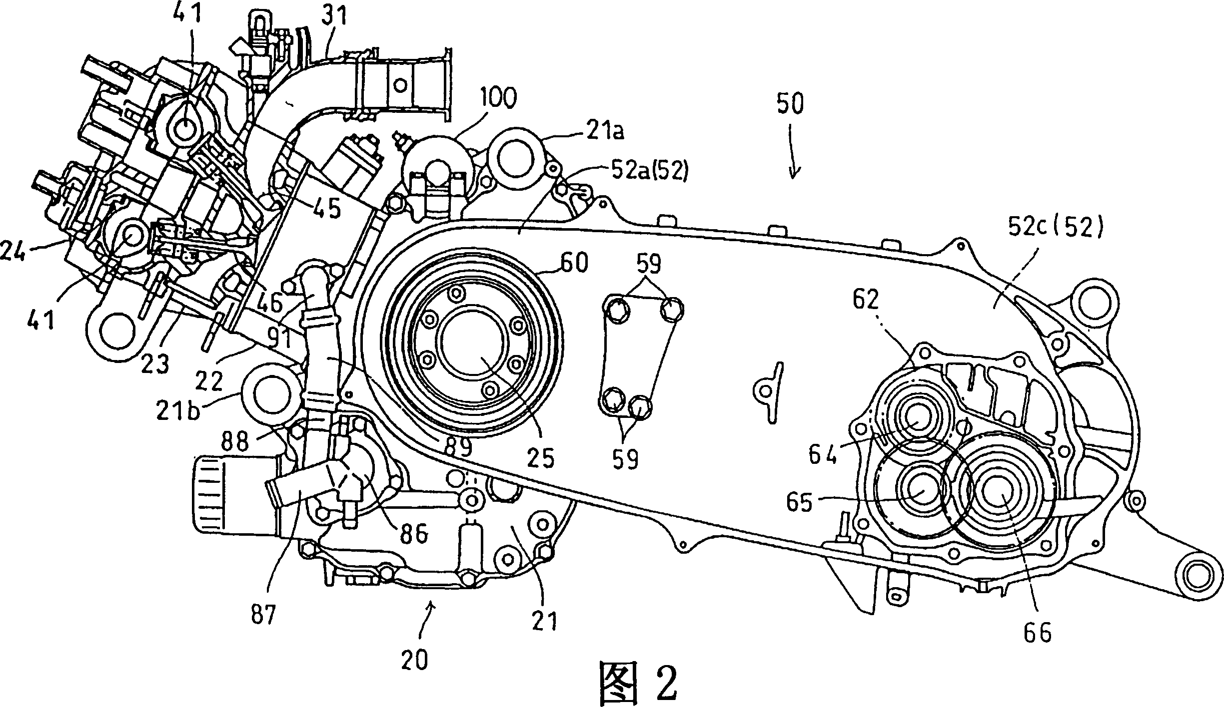
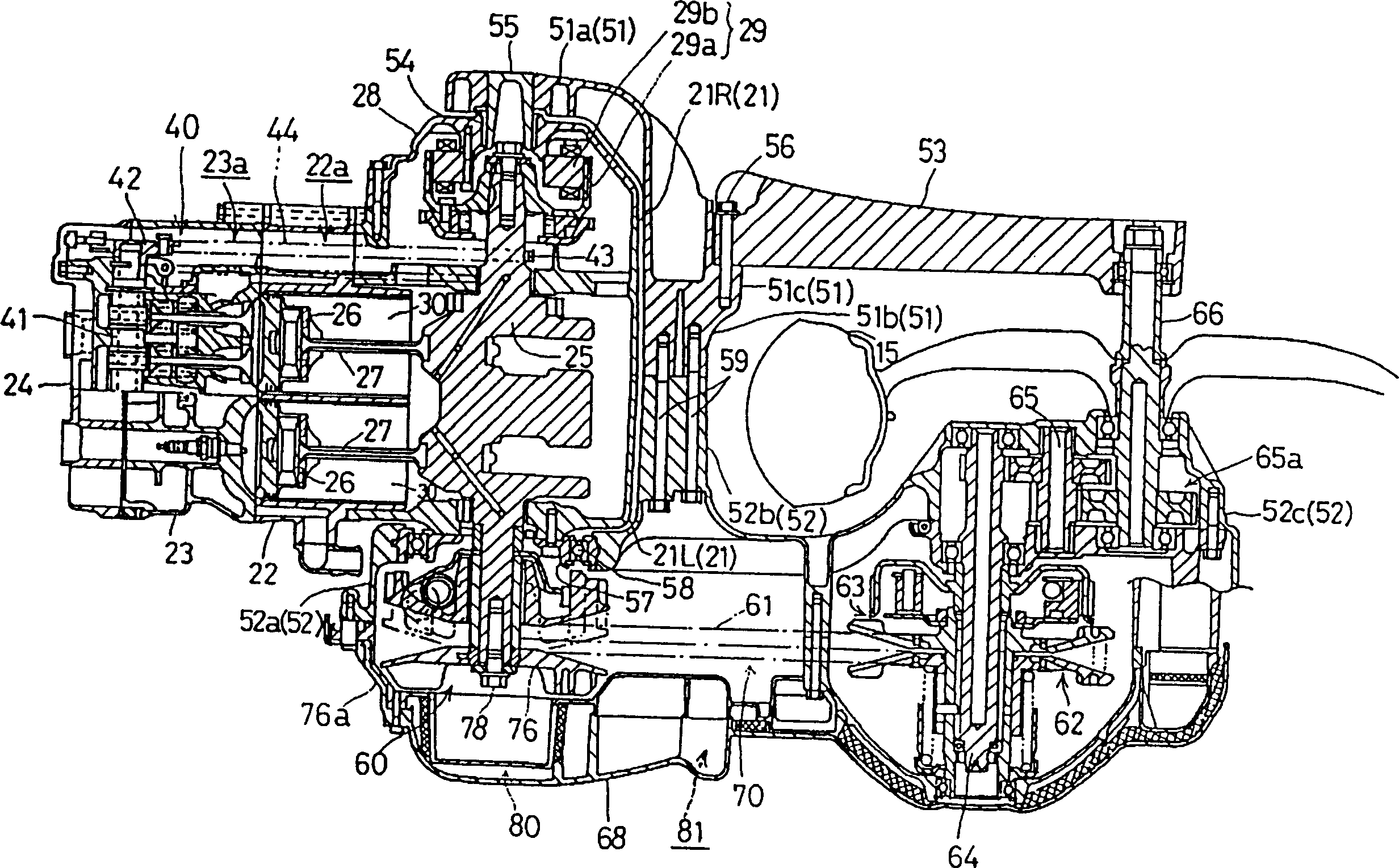
[0027] Refer below Figure 1~5 An embodiment of the present invention is described.

[0028] The internal combustion engine of this embodiment is suitable for a small two-wheeled motorcycle 1. The overall side view of the small two-wheeled motorcycle 1 is shown in figure 1 .

[0029] The frame of the scooter 1 has a structure in which a pair of left and right main pipes 3, 3 extend straight from the upper part of the head pipe 2 obliquely downward, as viewed from the side, and extend substantially horizontally to the rear from the head pipe 2 A pair of supporting pipes 4 and 4 are connected to the main pipes 3 and 3 and support the front parts of the main pipes 3 and 3.

[0030] Furthermore, a pair of left and right down pipes 5 and 5 extend from the middle part of the support pipes 4 and 4 to the left and right and extend downwards at a steeply inclined angle, forming the front vertical parts 5a and 5a, the lower ends of which are bent rearward. The rear ends of the central horiz...


PUM


Abstract

It is intended to provide a V belt type transmission capable of clamping a fixed pulley half firmly and capable of preventing the entry of dust and water into a fixed pulley half clamping threaded portion formed in an end portion of a crank shaft and thereby protecting the threaded portion from rust, etc. In a V belt type transmission wherein a V belt is entrained on a pulley 60, the pulley 60 comprising a fixed pulley half 76 fixed to an end portion of a crank shaft 25 and a movable pulley half 75 supported on the crank shaft 25 axially slidably in opposition to the fixed pulley half 76, the fixed pulley half 76 is clamped with a bolt 78 which is threadedly engaged with a female screw 25g formed inside an end portion of the crank shaft 25.

Description

Technical field [0001] The invention relates to a V-belt type transmission which transmits power through a V-belt set between pulleys. Background technique [0002] A V-belt is set up between a pair of pulleys composed of a fixed pulley half and a movable pulley half to transmit power in the form of continuously variable transmission. The fixed pulley half is fixed on the shaft end of the crankshaft. The fixed pulley half is fastened to the shaft end by screwing a nut on the external thread formed on the front end of the conventional crankshaft. [0003] E.g Figure 6 Shows the example described in JP 9-264391 A. [0004] This example involves a V-belt transmission for a small motorcycle, Figure 6 The pulley 02 on the crankshaft 01 side of the V-belt transmission is shown. [0005] On the shaft end of the crankshaft 01, an external thread 01a and a serrated portion are protrudingly formed, and a fixed pulley half 03 fitted on the serrated portion of the shaft end is fastened by ...

Claims


Application Information

Patent Timeline
Patent Type & Authority Patents(China)
IPC IPC(8): F16B9/02F16H9/18F16H57/023F16H57/035F16H57/04
CPCF16H57/0415F16H9/18F16H57/0489
Inventor 久我信二大山隆土屋粒二
Owner HONDA MOTOR CO LTD
Learn More