
Slot antenna device

An antenna device and slot antenna technology, which is applied to slot antennas, antennas, antenna parts, etc., can solve the problems of expensive, difficult antenna structure, and difficult manufacturing

Inactive Publication Date: 2005-04-13
SAMSUNG ELECTRONICS CO LTD
View PDF5 Cites 0 Cited by
  • Summary
  • Abstract
  • Description
  • Claims
  • Application Information

AI Technical Summary

Problems solved by technology

[0007] However, such an antenna structure is not easy to make very compact, it is impossible to work in multiple frequency bands or suitable impedance matching
In addition, its construction is complex due to the required tolerances for coupling to the feed making it difficult and expensive to manufacture and shielding around the RF circuit is not obvious

Method used


Image

  • Slot antenna device
  • Slot antenna device
  • Slot antenna device

Examples


Embodiment Construction

[0028] In the following description, which is intended to be illustrative rather than limiting, particular details are set forth in order to provide a thorough understanding of the invention. However, it will be apparent to those skilled in the art that the invention may be practiced in other embodiments that depart from these specific details. In other instances, detailed descriptions of known devices and methods are omitted so as not to obscure the description of the present invention.

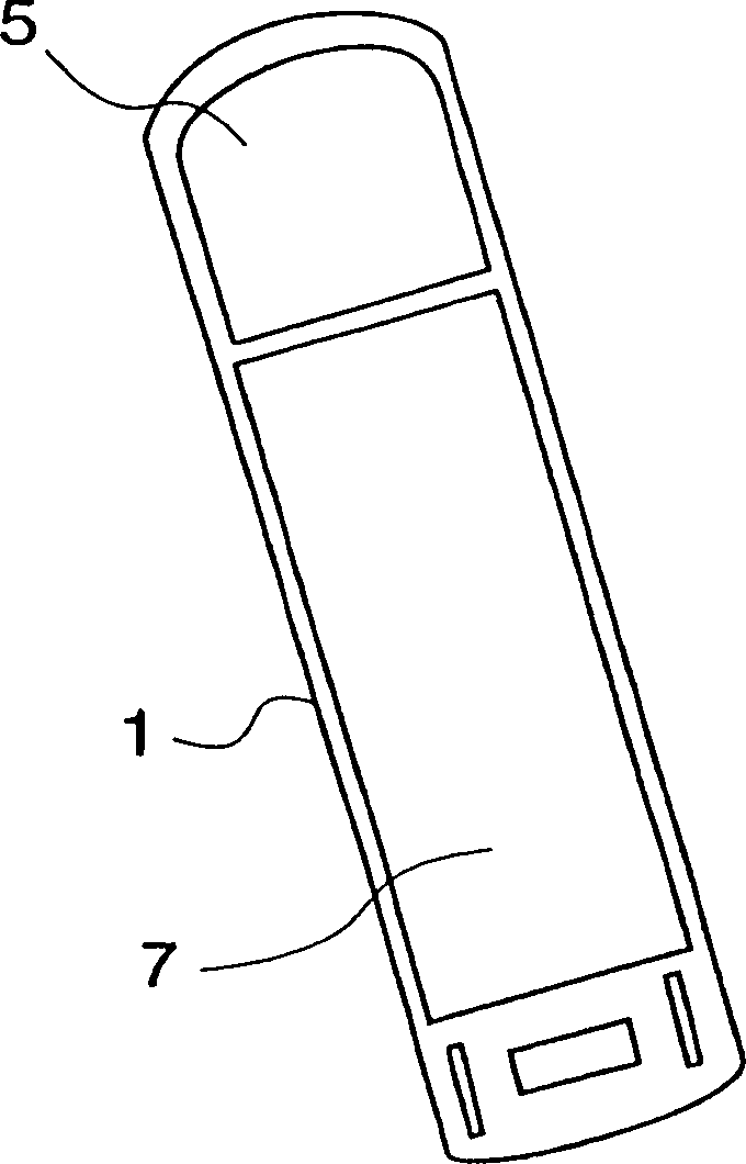
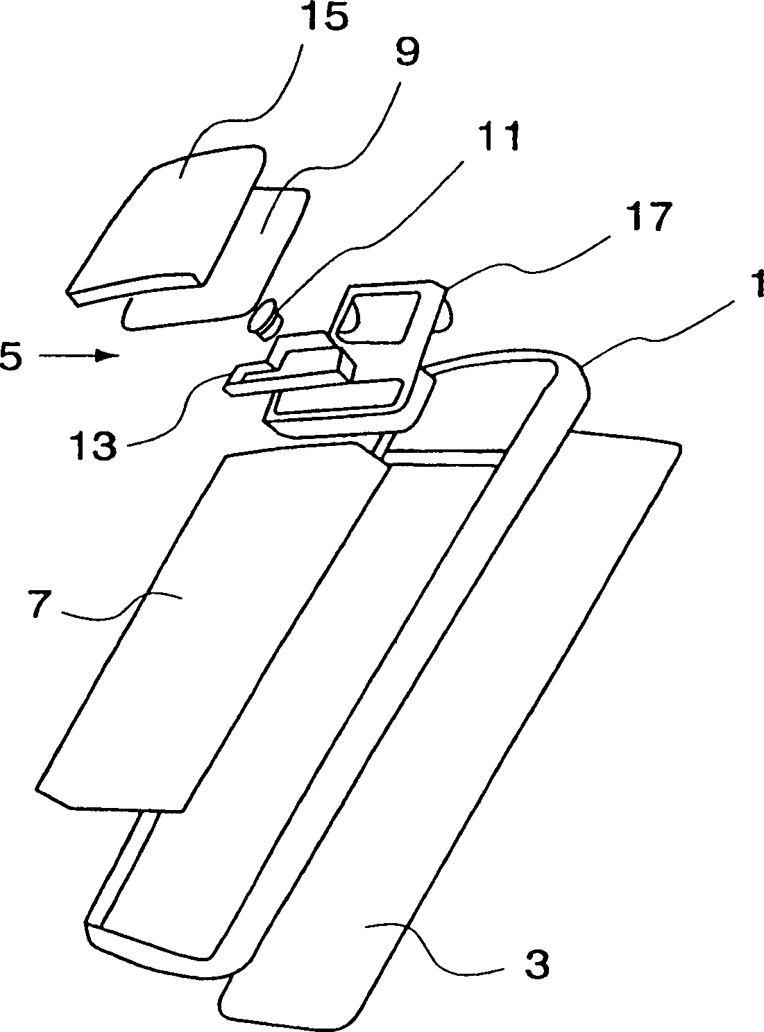
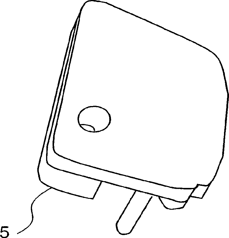
[0029] Figure 1a and 1b Indicates a cellular phone for transmitting and receiving radio frequency (RF) waves. The phone, shown in assembled and exploded perspective views, respectively, without housing as seen from behind. Reference numeral 1 in the figure is the chassis of the portable phone. Make sure that the main printed circuit board PCB3 of the phone is mounted on the front of the chassis 1. The PCB 3 includes any suitable signal processing circuitry (not shown) known in the art t...


PUM


Abstract

An apparatus connectable to a slot antenna comprising signal processing circuitry for transmitting and / or receiving radio frequency (RF) waves comprises a substantially planar conductive antenna element (23) having a slot (25) feeding and receiving locations are respectively placed on opposite sides of said slot (25); a substantially planar RF ground plane conductor is generally placed substantially parallel to said planar conductor antenna element; a ground connector connects said ground plane conductor to said ground point; and a feed connector connects said signal processing circuit to said feed point, wherein said antenna device is connectable to said radio communication equipment, so that said ground plane conductor will be placed at said between said conductive antenna element (23) and said signal processing circuitry to effectively shield said signal processing circuitry from said transmitted and / or received RF waves.

Description

technical field [0001] The present invention relates generally to the field of antennas, in particular to a slot antenna device for transmitting and / or receiving radio frequency waves, and to a portable radio communication device comprising such a slot antenna device. Background technique [0002] In today's radio communication systems high demands are placed on the operating efficiency and small size of the subscriber terminals thereof. Such high demands are placed on antenna devices for these user terminals which are compact and exhibit good antenna performance. [0003] To achieve compact size and robustness while maintaining high radiation efficiency, hand-held portable user terminals have used antenna devices comprising a helical element combined with an extendable whip antenna. At the same time, permanently extended external antenna devices are used extensively. [0004] Currently, attention has also been directed to antenna devices installed in housings of hand-held...

Claims


Application Information

Patent Timeline
Patent Type & Authority Patents(China)
IPC IPC(8): H01Q1/24H01Q13/10H01Q1/38H01Q23/00
CPCH01Q1/244H01Q1/38H01Q13/10H01Q23/00H01Q1/24
Inventor T·斯科尔迪利斯
Owner SAMSUNG ELECTRONICS CO LTD
Learn More