Hook commutator

A commutator, hook type technology, applied in the direction of rotating current collectors, current collectors, electrical components, etc., can solve the problems of reducing operating characteristics, reducing electrical characteristics, etc., to avoid excessive heat.

Inactive Publication Date: 2005-05-04
ROBERT BOSCH GMBH
View PDF1 Cites 1 Cited by
  • Summary
  • Abstract
  • Description
  • Claims
  • Application Information

AI Technical Summary

Problems solved by technology

This reduces the electrical properties such as the contact resistance between the carbon and the commutator segments or reduces the running characteristics of the carbon surface of the brushes or the life of the motor armature

Method used


Image

  • Hook commutator
  • Hook commutator

Examples


Embodiment Construction

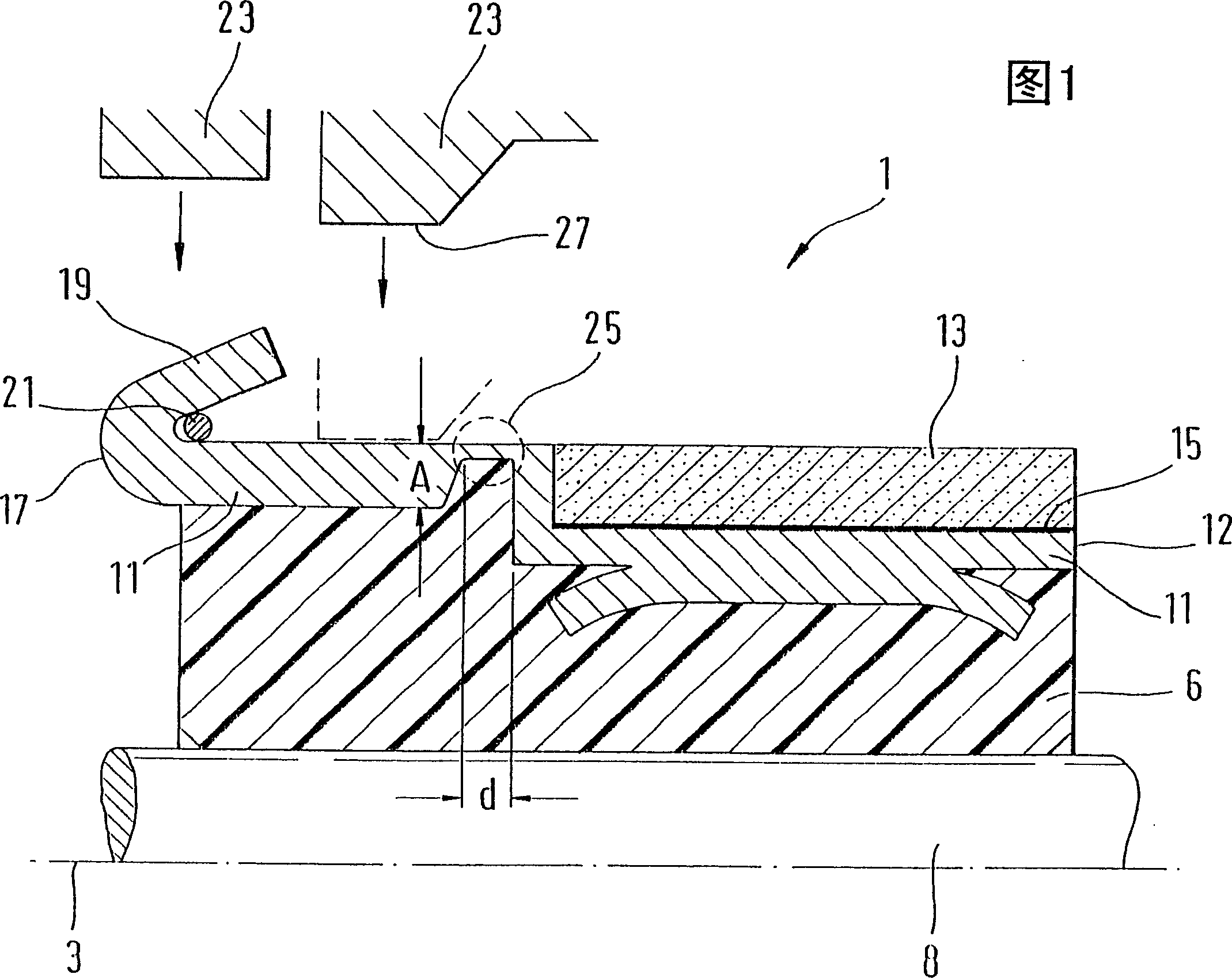
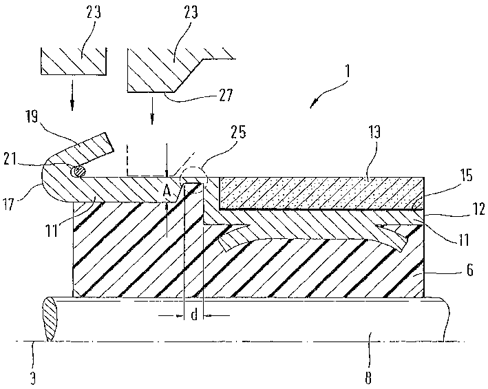
[0013] The drawing shows an otherwise known hook commutator 1 for an electric motor armature in axial cross-section. The hook commutator 1 has an axis of symmetry 3 . For example, a carrier 6 is mounted on the rotor shaft 8 of the motor armature. At least one commutator segment 11 made of electrically conductive material is fastened to the carrier 6 . This is done, for example, in that the commutator segments 11 are at least partially surrounded by injection molding of plastic, for example the material forming the carrier body 6 . However, the commutator segment 11 can also be fixed on the carrier 6 by other fixing methods.

[0014] Commutator segment 11 carries on one section at its one axial end 12 a carbon segment 13 which is fastened to commutator segment 11 via a soldered connection 15 . However, the invention is not restricted to the carbon segments 13 , but rather relates to all thermally sensitive segments connected to the commutator segments 11 . A commutator hook...


PUM


Abstract

In prior art hook commutators, the brazed connection (15) used to connect the carbon segments (13) to the segments (11) would become disengaged because during the thermal bonding used to secure the winding wires generate heat. The hook commutator (1) according to the invention has a low thermal conductivity between the commutator hook (19) and the carbon segment (13), thereby protecting the soldered connection (15) from overheating.

Description

technical field [0001] The invention relates to a hook commutator for an electric motor armature. Background technique [0002] Hook commutators for motor armatures have commutator segments to which the current is conducted via carbon brushes. The winding wires of the rotatable motor armature are electrically conductively connected to the commutator segments. Furthermore, in order to produce such a motor armature with hook commutator, the winding wires are wound on each commutator hook of the commutator segments of the hook commutator. During the necessary connection of the winding wires to the commutator hooks, it is important that there is always a good mechanical and electrical connection quality between the commutator hooks and the winding wires. Use thermal bonding (Hot-staking) as a connection process. Among them, the commutator hook is deformed so that the winding wire is clamped, and then a voltage is applied to heat the commutator hook and the winding wire, mainl...

Claims


Application Information

Patent Timeline
Patent Type & Authority Patents(China)
IPC IPC(8): H01R39/32H02K13/00
CPCH01R39/32H02K13/00
Inventor 乌尔里希·吕德克
Owner ROBERT BOSCH GMBH
Why Eureka
Try Eureka