Honeycomb body consisting of metal foils and method for the production thereof

A technology of honeycomb body and thin plate, applied in the direction of chemical instruments and methods, manufacturing tools, metal processing, etc., to achieve the effect of economical manufacturing, ensuring flow and wetting ability

Active Publication Date: 2011-04-13
EMITEC EMISSIONSTECHNIK
View PDF3 Cites 1 Cited by
  • Summary
  • Abstract
  • Description
  • Claims
  • Application Information

AI Technical Summary

Problems solved by technology

Previously, this problem could not be solved specifically for all application purposes of such honeycomb bodies

Method used


Image

  • Honeycomb body consisting of metal foils and method for the production thereof
  • Honeycomb body consisting of metal foils and method for the production thereof
  • Honeycomb body consisting of metal foils and method for the production thereof

Examples


Embodiment Construction

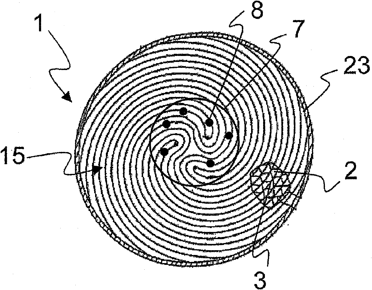
[0055] figure 1 A schematic end view of a honeycomb body 1 is shown, which consists of a smooth sheet metal 2 and a structured sheet metal 3 , which are arranged in a housing 23 . For the present case, the exact shape of the honeycomb structure 15 formed in the housing by the wound sheets 2 , 3 is not critical. In fact, the invention is applicable to metal honeycomb bodies of all known shapes. For example, a region 7 is mentioned here, in which a connection point 8 is formed, for example by brazing, between adjacent sheet metal sheets 2 , 3 , so that the honeycomb body 1 has a high stiffness at this connection point. Separate connection points 8 are optionally provided in this region 7 , which can be positioned in any desired manner within the honeycomb body 1 , of course also in relation to the connection between the metal sheets 2 , 3 and the housing 23 .

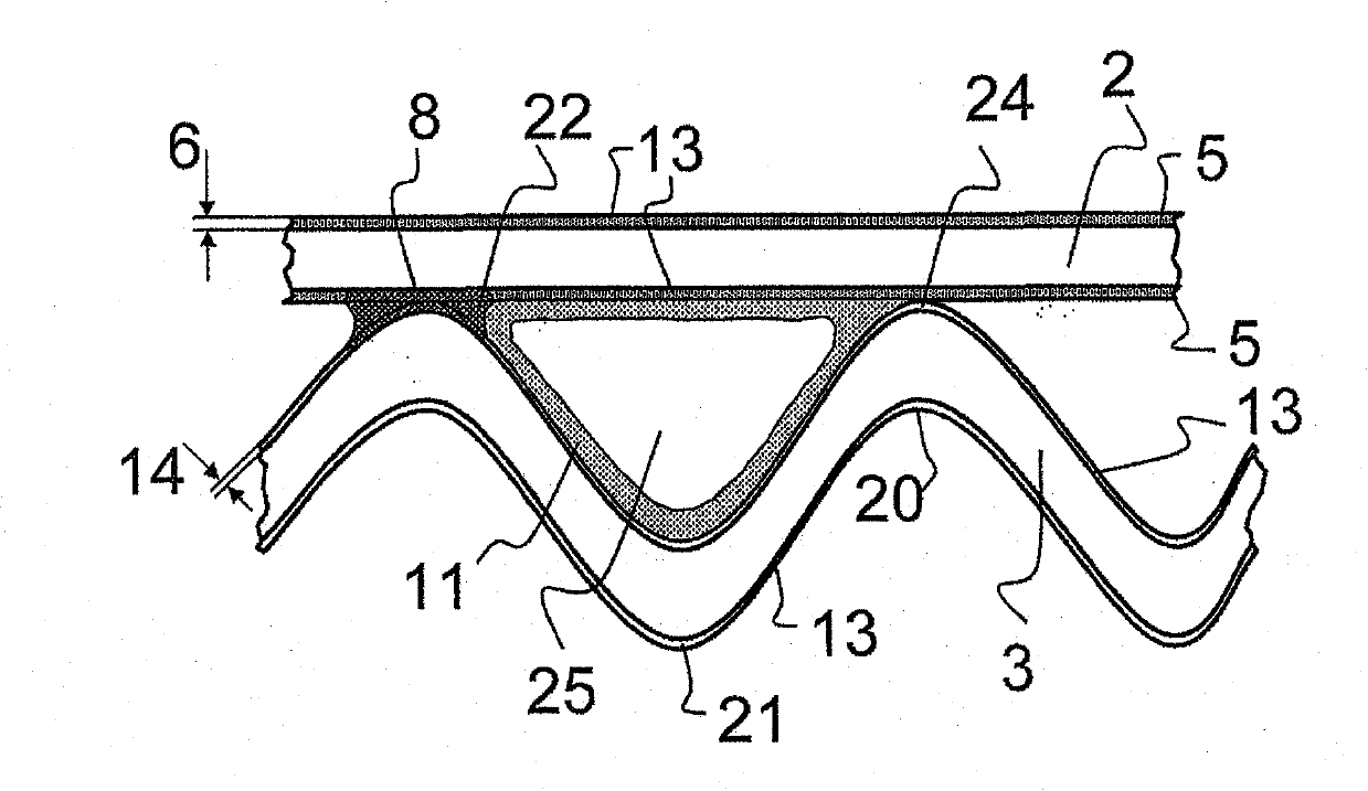
[0056] figure 2 The contact points 24 between the smooth sheet metal 2 and the structured sheet metal 3 in the hone...


PUM

PropertyMeasurementUnit
mean roughnessaaaaaaaaaa
thicknessaaaaaaaaaa

Abstract

The invention relates to a honeycomb body (1) consisting of smooth and textured metal foils (2, 3) and to a method for the production of said body. The smooth foils (2) have different average roughnesses (12) or different oxide layer thickneses (6, 14) in relation to the textured foils (3).

Description

technical field [0001] The invention relates to a honeycomb body formed from at least one smooth metal sheet and at least one structured metal sheet and to a method for producing the honeycomb body, the honeycomb body and the method for the honeycomb body in particular It is an application in the exhaust system of an internal combustion engine in a motor vehicle. Background technique [0002] Metal sheets have long been used in the manufacture of honeycomb bodies, especially for exhaust systems of internal combustion engines. Due to the high temperatures in this application, steels containing chromium and aluminium, which are particularly resistant to high temperature corrosion, are mostly used. Here, a general thin plate has a thickness of 20 μm to 180 μm (micrometer), and is usually produced by rolling. When using such sheets for metal honeycomb bodies and other exhaust gas purification components, special requirements must be placed on the surface. [0003] Honeycomb b...

Claims


Application Information

Patent Timeline
Patent Type & Authority Applications(China)
IPC IPC(8): F01N3/28B01J35/04
CPCB23K1/20B01J35/04B23K2201/006B23K1/0012F01N3/281B23K1/0014F01N2330/04B23K2201/14B23K2101/006B23K2101/14Y02A50/20
Inventor R·布吕科
Owner EMITEC EMISSIONSTECHNIK
Why Eureka
Try Eureka