Loop antenna and antenna holder therefor

A technology of loop antenna and cage, applied in the direction of loop antenna, variable reactance loop antenna, antenna, etc., can solve the problems of large installation space, impossible to obtain effective gain of antenna, difficult to find installation area, etc., to achieve improvement Effective buff effect

Inactive Publication Date: 2005-05-11
PANASONIC CORP
View PDF0 Cites 0 Cited by
  • Summary
  • Abstract
  • Description
  • Claims
  • Application Information

AI Technical Summary

Problems solved by technology

[0004] In the conventional loop antenna described above, there is a problem that it is impossible to obtain the effective gain inherent in the antenna due to the impedance loss of the welded portion of the capacitor 4 and the loop antenna parts 19 and 20 on the substrate 8.
[0005] Also, personal option call receivers have become very compact in recent years, and it can be difficult to find a mounting area
If a conventional antenna holder 6 is used, since the capacitor 4 is located on the substrate 8, the capacitor 4 must be welded with the antenna parts 19 and 20 on the substrate 8, which requires a larger installation space

Method used


Image

  • Loop antenna and antenna holder therefor
  • Loop antenna and antenna holder therefor
  • Loop antenna and antenna holder therefor

Examples


no. 1 example

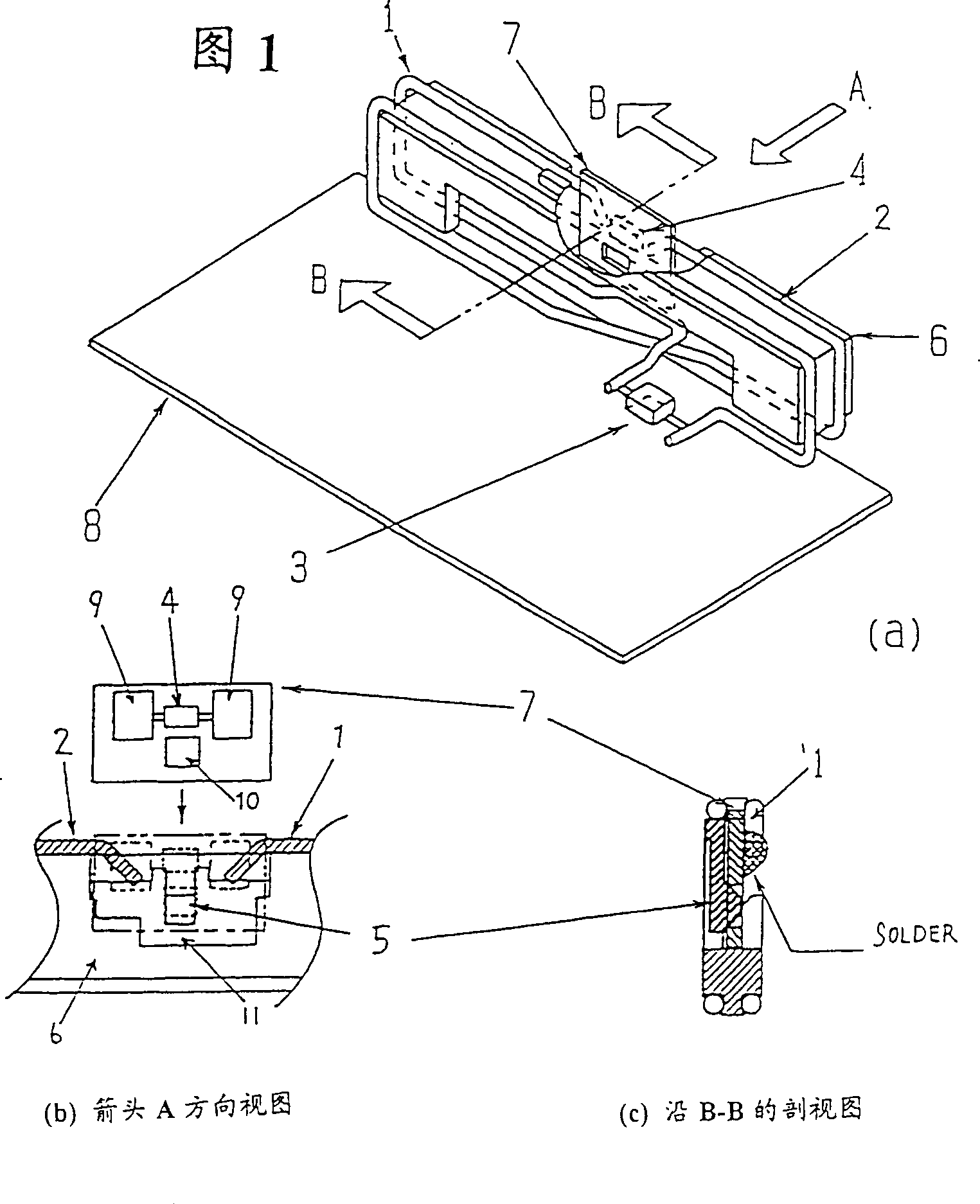
[0029] In the first embodiment of the present invention, it can be seen from the perspective view showing a loop antenna structure in Fig. The capacitor 4 inserted in the manner of the loop antenna parts 1 and 2 and the impedance matching indexing member 3 for adjusting the antenna and establishing a match with a high frequency circuit are constituted.

[0030] An additional substrate 7 equipped with a capacitor 4 is fixedly installed by a fixed claw 5 of an antenna holder 6, and is connected to it by welding a pair of base surfaces 9 on the additional substrate 7 to the loop antenna components 1 and 2 .

[0031] It should be noted that the fixing claw 5 is integrally formed when the antenna holder 6 is formed, and its material is resin.

[0032] In addition, FIG. 1(b) is a view in the direction of arrow A in FIG. 1(a), and shows a separate state before the additional substrate 7 is mounted on the antenna holder 6. As shown in FIG. The capacitor 4 and the bases 9 electricall...

no. 2 example

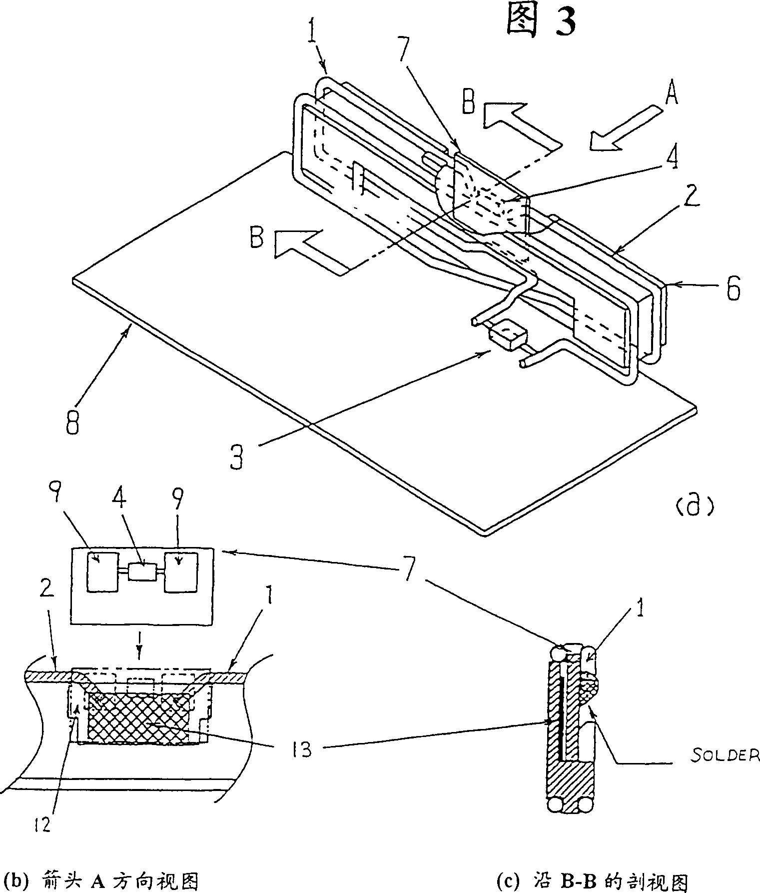
[0038] In a second embodiment of the present invention, it can be clearly seen from the perspective view showing a loop antenna structure in Fig. Capacitor 4 inserted in a manner divided into loop antenna parts 1 and 2 and impedance matching indexer 3 for adjusting the antenna and establishing matching with a high-frequency circuit. The additional substrate 7 that capacitor 4 is housed is fixedly mounted on the antenna holder 6 by bonding means such as pressure-sensitive adhesive double-sided tape 13 or a combination device, and passes through a pair of base surfaces 9 of the additional substrate 7 and the loop antenna part 1 and 2 are connected by welding.

[0039] In addition, FIG. 3( b ) is a view in the direction of arrow A in FIG. 3( a ), and shows a state where the additional substrate 7 is alone before the additional substrate 7 is mounted on the antenna holder 6 . The capacitor 4 and the base area 9 electrically connected to the capacitor 4 on both sides are arranged ...


PUM


Abstract

A closed loop consists of a loop antenna element which also acts as an inductance, capacitors inserted to divide the loop antenna into loop antenna elements, and an impedance matching scale for adjusting the antenna and establishing a match to a high-frequency circuit. An additional substrate containing capacitors is fixedly mounted by a fixing claw of an antenna holder, and is connected thereto by welding a pair of base surfaces on the additional substrate to the loop antenna part. As a result, the effective gain of the antenna can be enhanced and the substrate space can be effectively used.

Description

technical field [0001] The present invention relates to a loop antenna for a portable receiver and its antenna holder, and more particularly to a loop antenna having an additional substrate capable of mounting and fixing a capacitor. Background technique [0002] A portable receiver is specifically a person-selected call receiver such as a pager which is usually carried by a user so that the whole device is compact and a loop antenna which may be incorporated in the receiver is used as the antenna of the receiver, And an antenna holder is generally used as a holder for fixing the loop antenna. [0003] The circuit diagram of a conventional loop antenna is shown in Figure 4 As shown in (a), it is arranged as a closed loop consisting of loop antenna elements 19 and 20 which also act as inductance, a capacitor 4 inserted in such a way that the loop antenna is divided into loop antenna elements 19 and 20, and a capacitor 4 for adjusting the antenna and connecting with a high T...

Claims


Application Information

Patent Timeline
Patent Type & Authority Patents(China)
IPC IPC(8): H01Q1/24H01Q1/12H01Q7/00H01Q11/12
CPCH01Q1/12H01Q7/005H01Q11/12
Inventor 长谷川邮望月信贵西川健一池田一公菅原秀一
Owner PANASONIC CORP
Why Eureka
Try Eureka