
Front-end circuit of high-speed optical receiver and its low-noise processing method

A technology of optical receiver and front-end circuit, which is applied in the field of high-speed optical communication transceiver chips, can solve the problems of poor noise performance of high-speed optical receivers, etc., and achieve the effects of improving sensitivity, increasing effective gain, and improving output signal-to-noise ratio

Active Publication Date: 2020-05-22
PHOTONIC TECH SHANGHAI CO LTD
View PDF5 Cites 0 Cited by
  • Summary
  • Abstract
  • Description
  • Claims
  • Application Information

AI Technical Summary

Problems solved by technology

[0004] In view of the shortcomings of the prior art described above, the purpose of the present invention is to provide a front-end circuit of a high-speed optical receiver and a low-noise processing method thereof, which are used to solve the problem of poor noise performance of a high-speed optical receiver of a CMOS process in the prior art. question

Method used


Image

  • Front-end circuit of high-speed optical receiver and its low-noise processing method
  • Front-end circuit of high-speed optical receiver and its low-noise processing method

Examples


Embodiment

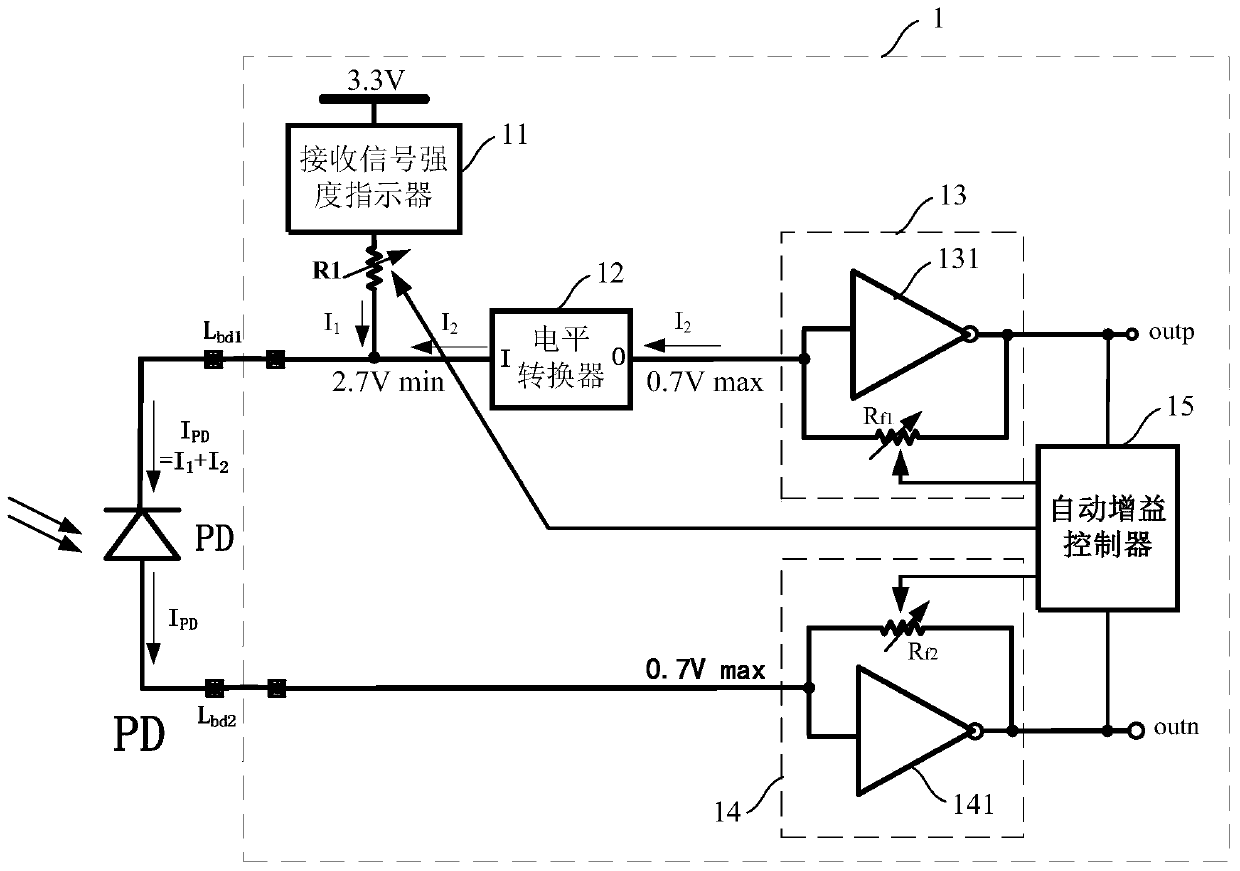
[0040] Such as figure 1 As shown, the present invention provides a front-end circuit 1 of a high-speed optical receiver, and the front-end circuit 1 of the high-speed optical receiver includes:

[0041] Received signal strength indicator 11 , first resistor R1 , level shifter 12 , first transimpedance amplifier 13 , second transimpedance amplifier 14 and automatic gain controller 15 .

[0042] Such as figure 1 As shown, the signal strength indicator (RSSI, Received Signal Strength Indicator) 11 is connected between the power supply voltage VDD and the first resistor R1, and is used to display the intensity of the received laser signal.

[0043] Specifically, the photodiode converts the laser signal received by the PD into an electrical signal, and the current flowing through the signal strength indicator is equal to the common-mode average value of the photocurrent of the photodiode PD, because the difference between the optical power and the current The mathematical relatio...


PUM


Abstract

The invention provides a front-end circuit of a high-speed optical receiver and a low-noise processing method thereof. The front-end circuit comprises a first resistor connected between a power supplyvoltage and a cathode of a photodiode; a level shifter connected to a photodiode cathode; a first transimpedance amplifier connected to the level shifter; a second transimpedance amplifier connectedto the photodiode anode; an automatic gain controller connected to the first and second transimpedance amplifiers and configured to compare the magnitude of the output signal of the first and second transimpedance amplifiers with a reference value, and adjust the first resistor, the first and second transimpedance amplifiers according to the comparison result, thereby keeping the magnitude of theoutput signal of the first and second transimpedance amplifiers constant. The invention adopts the mode of differential input and differential output to increase the output swing by two times, improvethe effective gain of the circuit, effectively improve the output signal-to-noise ratio of the transimpedance amplifier without increasing the output noise of the transimpedance amplifier, and further improve the sensitivity of the transimpedance amplifier.

Description

technical field [0001] The invention relates to the field of high-speed optical communication transceiver chips, in particular to a front-end circuit of a high-speed optical receiver and a low-noise processing method thereof. Background technique [0002] At present, the bandwidth demand of high-speed interconnection networks such as data centers is getting higher and higher. Due to its disadvantages in cost and performance, the traditional electrical interconnection is increasingly replaced by optical fiber communication with low price, large capacity, small crosstalk, and strong anti-electromagnetic interference. obvious. However, as the core of optical communication interconnection, the current high-speed optical communication transceiver chips (drivers, cross-group amplifiers, limiting amplifiers, and clock data recovery circuits, etc. are designed and manufactured using traditional SiGe / GaAs and other processes, and their bandwidth and noise performance is superior. Bu...

Claims


Application Information

Patent Timeline
Patent Type & Authority Patents(China)
IPC IPC(8): H04B10/69
CPCH04B10/69H04B10/693
Inventor 王俊成姜培陈学峰
Owner PHOTONIC TECH SHANGHAI CO LTD
Learn More