
Projection tube

A projection tube and projection technology, applied in the field of projection tubes, can solve problems such as increased light spot size, poor definition, and impact on projection effects, and achieve the effects of enhanced pre-focusing, improved voltage resistance, and reduced amplification factor

Inactive Publication Date: 2005-05-25
CAIHONG GRP ELECTRONICS CO LTD
View PDF0 Cites 1 Cited by
  • Summary
  • Abstract
  • Description
  • Claims
  • Application Information

AI Technical Summary

Problems solved by technology

[0002] Most of the existing black-and-white or color projection tubes have low brightness, poor definition, poor voltage resistance, and unreasonable design of the electron gun, especially when the outer diameters of the first anode electrode G3 and the focusing electrode G4 are equal. As the current increases, the size of the light spot also increases, which affects the projection effect. The existing technology cannot meet the requirements of the definition of the projection tube.
At the same time, the electrode flanging treatment is not reasonable enough, and it cannot meet the pressure resistance requirements of the projection tube.

Method used


Image

  • Projection tube
  • Projection tube
  • Projection tube

Examples


Embodiment Construction

[0018] Accompanying drawing is the specific embodiment of the present invention.

[0019] The content of the present invention will be further described below in conjunction with the accompanying drawings.

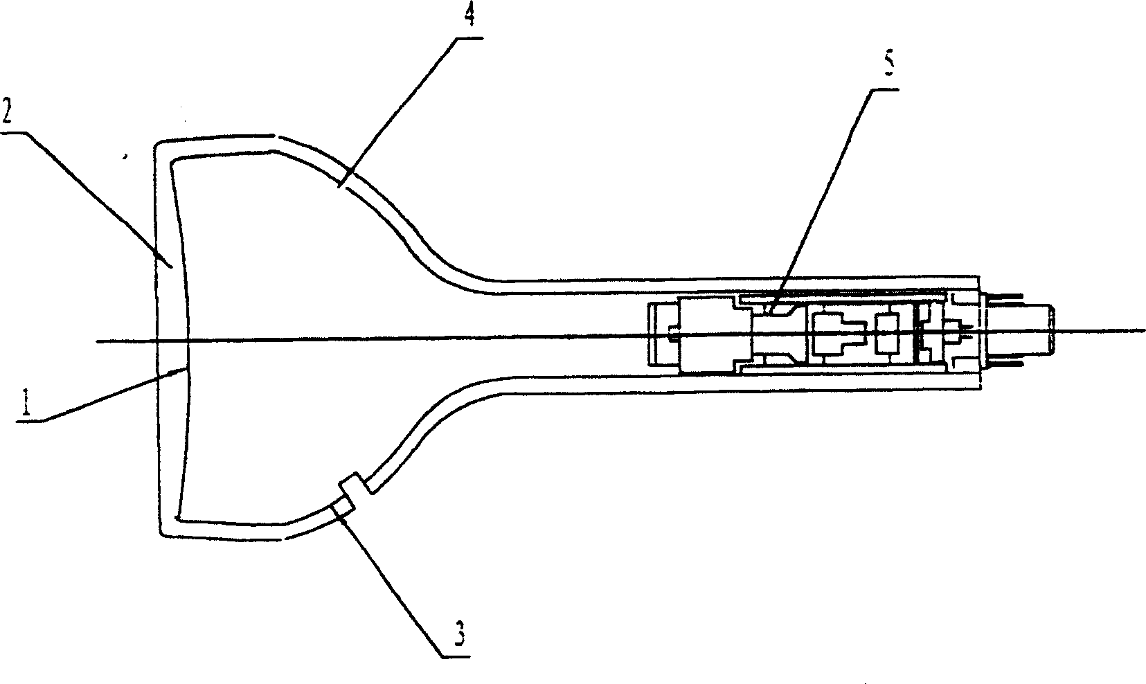
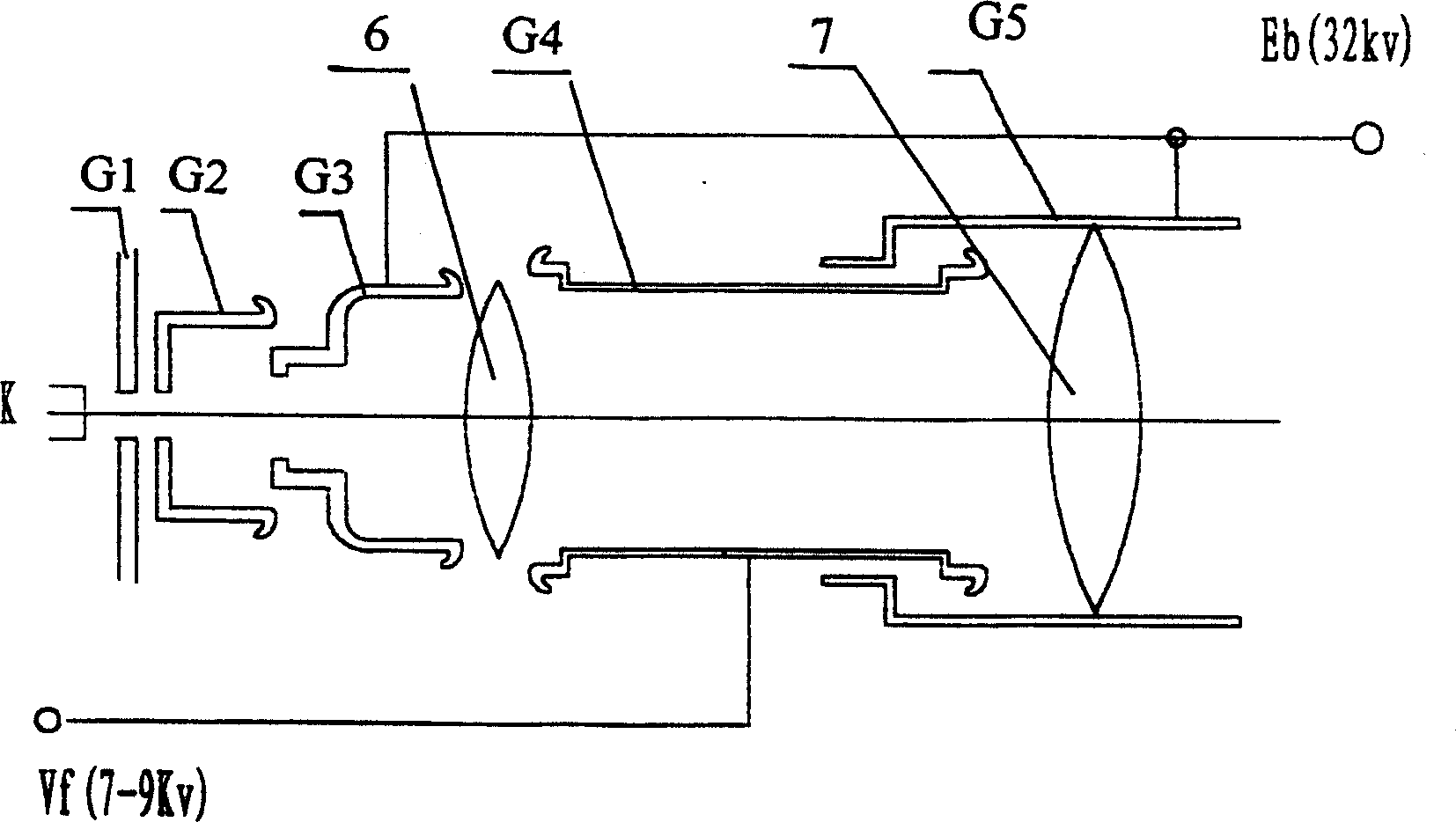
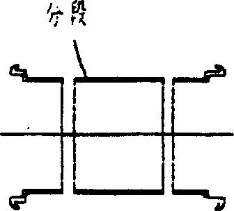
[0020] refer to figure 1 , 2 As shown, phosphor film 1 is coated on the negative curved screen of glass bulb 2, graphite layer 3 is coated on the neck of the projection tube, aluminum film 4 is coated in the tube, and electron gun 5 is installed at the tail of the cone. Said electron gun 5 is also Including the modulating electrode G1, the cathode K is placed in front of the modulating electrode G1, the accelerating electrode G2 is arranged behind the modulating electrode G1, the first anode electrode G3 is arranged behind the accelerating electrode G2, and the focusing electrode G4 is arranged behind the first anode electrode G3 , the second anode electrode G5 is set behind the focus electrode G4, and the ports of the acceleration electrode G2, the first anode electrode...


PUM


Abstract

A projection tube, the negative curved surface of the projection tube glass shell is coated with fluorescent powder, the neck of the projection tube is coated with graphite, the inside of the tube is coated with aluminum film, and the tail of the projection tube is equipped with an electron gun. The electron gun is composed of a modulation electrode (G1), an acceleration electrode (G2), The first anode electrode (G3), the focus electrode (G4), the second anode electrode (G5), the acceleration electrode (G2), and the first anode electrode (G3) form a pre-focus, the first anode electrode (G3), the focus electrode ( G4) constitutes the auxiliary lens, the focusing electrode (G4) and the second anode electrode (G5) constitute the main lens, the anode voltage of 32KV is applied to the first anode electrode (G3) and the second anode electrode (G5), and the focusing voltage of 7-9KV Add to focusing electrode (G4). The invention has high focusing voltage, single-potential electrostatic focusing electron gun, enhanced pre-focusing effect, improved definition of projection tubes, and is suitable for producing projection tubes with various specifications such as 16, 19, and 22 centimeters.

Description

technical field [0001] The invention relates to a projection tube, in particular to a projection tube used in a rear projection TV. Background technique [0002] Most of the existing black-and-white or color projection tubes have low brightness, poor definition, poor voltage resistance, and unreasonable design of the electron gun, especially when the outer diameters of the first anode electrode G3 and the focusing electrode G4 are equal. As the current increases, the size of the light spot also increases, which affects the projection effect, and the prior art cannot meet the requirement of the definition of the projection tube. At the same time, the electrode flanging treatment is not reasonable enough, and it cannot meet the pressure resistance requirements of the projection tube. Contents of the invention [0003] The object of the present invention is to provide a projection tube with high brightness, high definition and high withstand voltage. [0004] Realize the te...

Claims


Application Information

Patent Timeline
IPC IPC(8): H01J9/00H01J29/48
Inventor 刘明东李宏新冯星张青霞贺群胜
Owner CAIHONG GRP ELECTRONICS CO LTD
Features
  • Generate Ideas
  • Intellectual Property
  • Life Sciences
  • Materials
  • Tech Scout
  • Unparalleled Data Quality
  • Higher Quality Content
  • 60% Fewer Hallucinations
Learn More