
Battery body

A technology for batteries and battery packs, applied to batteries, secondary batteries, battery pack components, etc., can solve the problems of inability to form resin injection parts, less rise of PTC components, and inability to properly cut off power supply, and achieve easy packaging. Override, the effect of preventing the increase in resistance value

Inactive Publication Date: 2005-08-10
KYOCERA CORP
View PDF1 Cites 5 Cited by
  • Summary
  • Abstract
  • Description
  • Claims
  • Application Information

AI Technical Summary

Problems solved by technology

[0007] However, in the above-mentioned battery body, since the PTC element is arranged on the surface of the battery pack, even if the PTC element is heated due to overcurrent, the battery pack will take heat from the PTC element and prevent the temperature of the PTC element from rising.
Therefore, the increase in the resistance value of the PTC element is small, and the power supply from the battery pack cannot be properly cut off, so there is a problem that the protection of electronic equipment is insufficient.
[0008] In addition, since the PTC element is placed in contact with the surface of the battery pack, no resin injection molded portion can be formed between the PTC element and the surface of the battery pack, and there is a risk of the PTC element and the surface of the battery pack being peeled off from each other.

Method used


Image

  • Battery body
  • Battery body
  • Battery body

Examples


Embodiment Construction

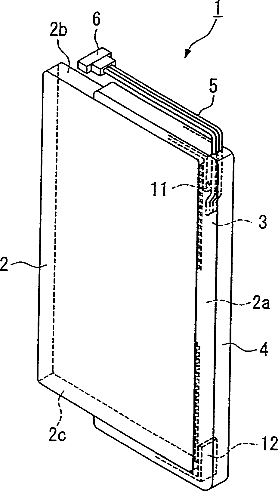
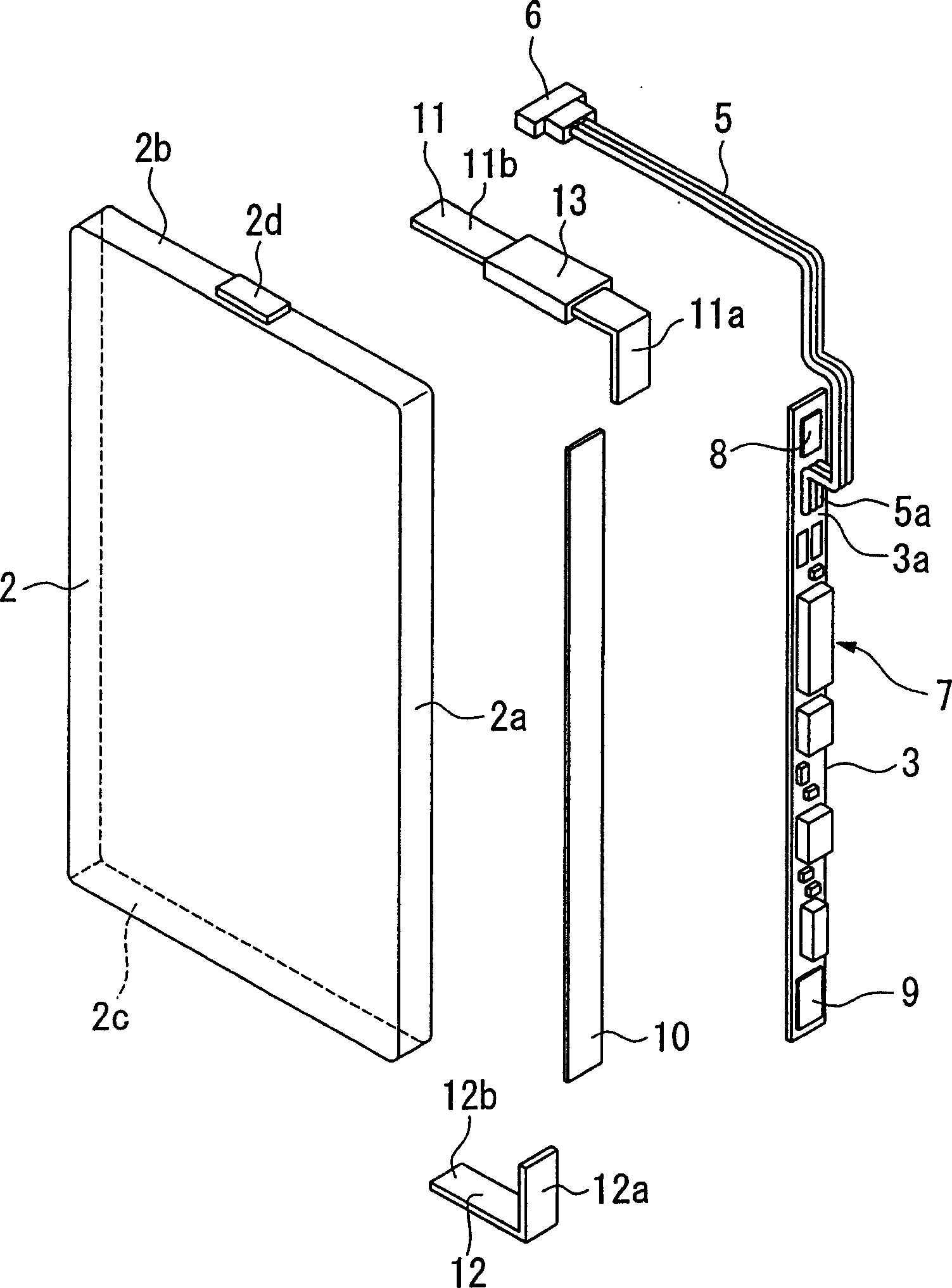
[0033] Figure 1 to Figure 5 An example of the present invention is shown. Such as figure 1 As shown, the storage battery body 1 of the present embodiment is a storage battery body used in a portable electronic device such as a mobile phone, and has a storage battery pack 2 in the shape of a rectangular plate, and a side surface 2a disposed along the storage battery pack 2 The circuit board 3, and the resin injection molding part 4 that wraps the circuit board 3 and is fixed on the side surfaces 2a, 2b, 2c of the battery pack 2, and the cable 5 drawn out from the resin injection molding part 4 and is arranged on the front end of the cable 5 , and form a connecting terminal 6 electrically connected to the electronic instrument.

[0034] On the side 2b of the battery pack 2, such as figure 2 As shown, the protruding negative terminal 2d is arranged in the center, and the other surfaces are positive terminals. In addition, the protruding negative terminal 2d is electrically ...


PUM


Abstract

A battery includes a battery cell, a circuit base board which is connected to terminals in the battery cell electrically via connection members, a heat protecting element, disposed in the connecting members, in which electric resistance increases according to an increase in a temperature therein, and a resin mold section which covers the circuit base board, the connecting members, and the heat protecting element so as to fix thereof on the battery cell. The heat protecting element is disposed so as to be separated from a surface of the battery cell via the resin mold section. By doing this, it is possible to increase electric resistance in the heat protecting element due to overcurrent normally in a battery which is provided with a heat protecting element so as to protect the electronic apparatus such as a mobile phone.

Description

technical field [0001] The invention relates to a storage battery body, which has a heating protection element for protecting electronic equipment from overcurrent. Background technique [0002] In the past, as a storage battery body installed in portable electronic devices such as mobile phones, portable terminal devices, and video cameras, it was provided that a storage battery pack was provided, and it was electrically connected to electronic components and electronic equipment that control the charging and discharging of the storage battery pack. A circuit board for connecting terminals, and a battery body integrally fixing these battery packs and a resin molded portion of the circuit board (for example, refer to Patent Document 1). [0003] These storage battery packs and circuit boards are electrically connected through connecting members, and PTC (Positive Temperature Cofficient) elements (heat protection elements) are provided on these connecting members. [0004] T...

Claims


Application Information

Patent Timeline
Patent Type & Authority Patents(China)
IPC IPC(8): H01M2/34G05D23/24H01M2/10H01M6/50H01M10/42
CPCY02E60/12H01M10/5026H01M2/348H01M10/425H01M2200/106H01M10/5032H01M10/637H01M10/647H01M50/581Y02E60/10
Inventor 福井繁昭
Owner KYOCERA CORP
Learn More