
Improved method of measuring vacuum pressure in sealed vials

A technology of vacuum pressure and internal pressure, applied in the application of electrical devices to test fluid tightness, vacuum gauges using ionization effects, etc., can solve problems such as increased errors and delays that have not been eliminated, and achieve fast voltage jump rates and fast The effect of the test

Inactive Publication Date: 2005-08-31
大卫·约翰·波威尔
View PDF2 Cites 0 Cited by
  • Summary
  • Abstract
  • Description
  • Claims
  • Application Information

AI Technical Summary

Problems solved by technology

[0009] Although patent DE 4126275 A1 discloses a method for minimizing the ionization delay, the delay is not eliminated and still causes a progressive increase in error with the increase of the voltage transition rate (required for high-speed automatic test procedures)

Method used


Image

  • Improved method of measuring vacuum pressure in sealed vials
  • Improved method of measuring vacuum pressure in sealed vials
  • Improved method of measuring vacuum pressure in sealed vials

Examples


Embodiment Construction

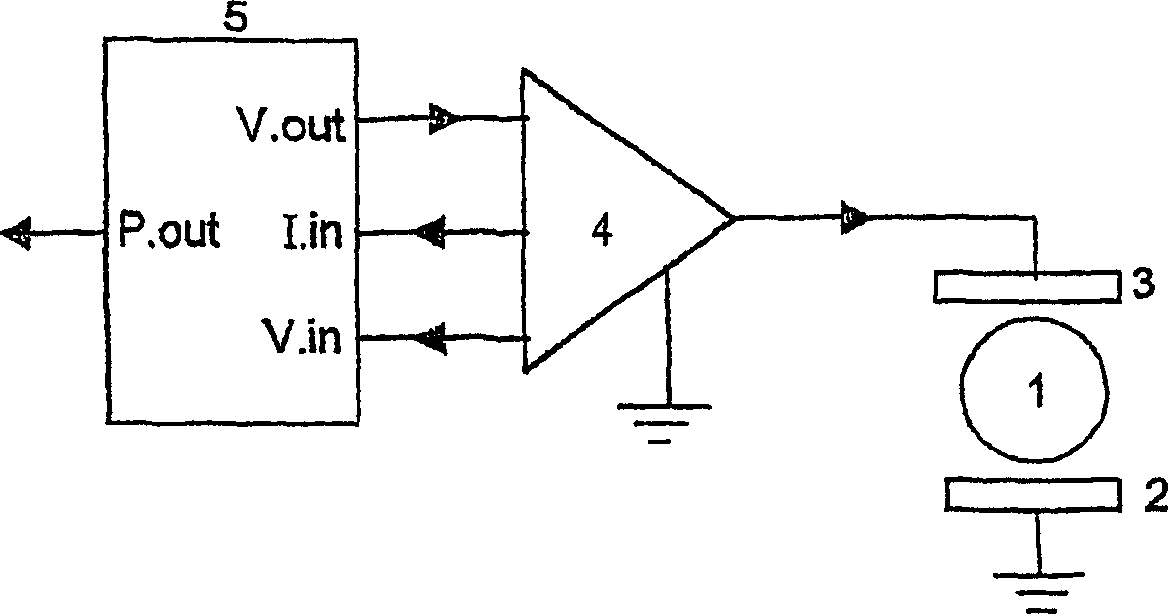
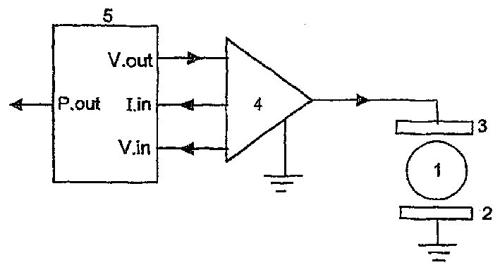
[0026] refer to figure 1 , the container 1 to be tested is located between a grounded electrode 2 and an electrode 3 driven by a high-frequency, high-voltage source 4, which is typically capable of generating a voltage of 20,000 volts and a frequency of hundreds of thousands Weekly voltage.

[0027] The controller 5 is provided with input signals representing the electrode voltage "V.in" and the electrode current "I.in". The controller 5 is further provided with a means of controlling the output voltage of the source 4 through the output signal "V.out".

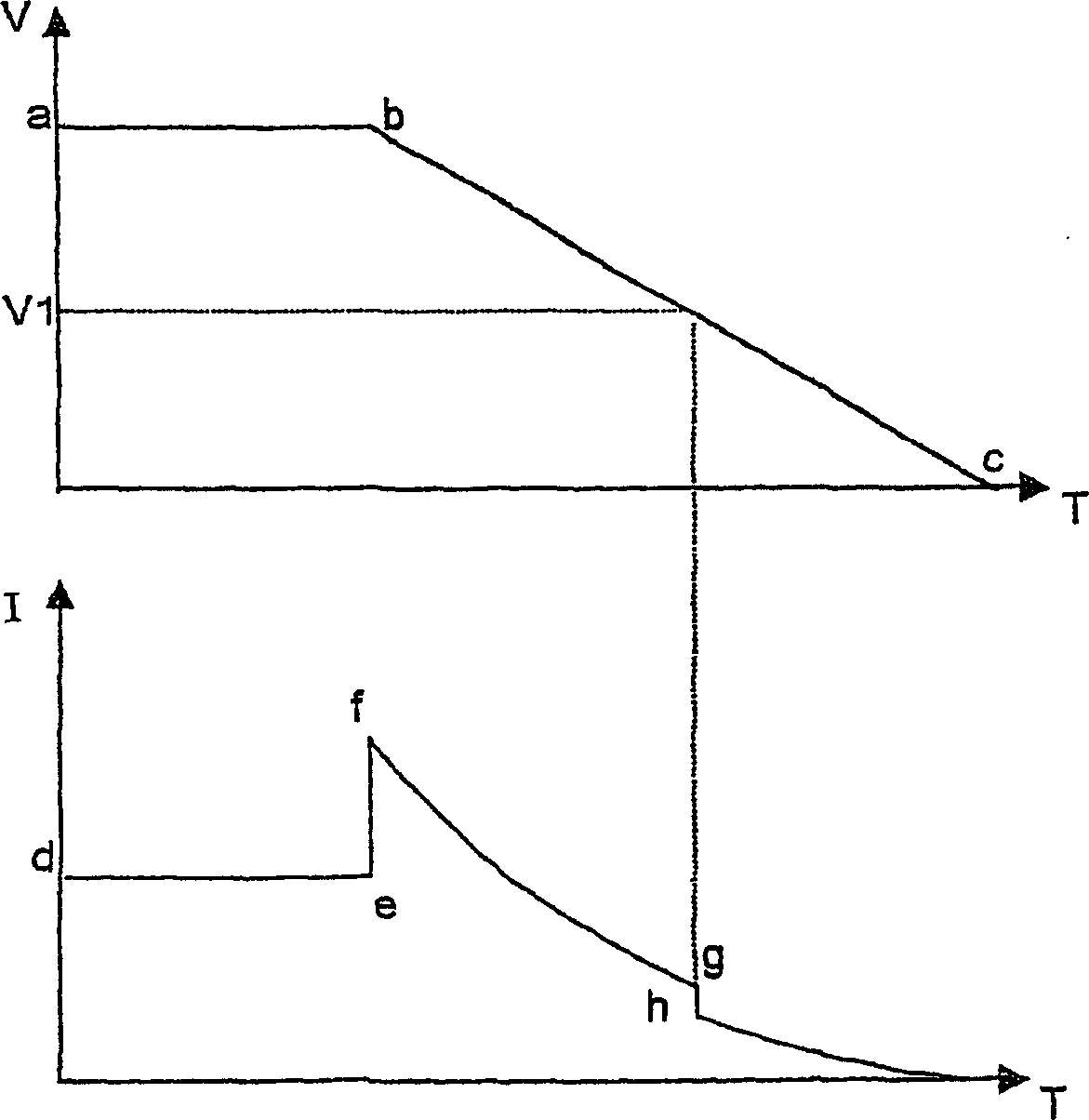
[0028] refer to figure 2 , the graph shows the electrode voltage "V" and the corresponding electrode current "I" during a typical test sequence. Typical time periods for test sequences are on the order of a few hundred milliseconds. At the beginning of the pressure measurement sequence, the maximum voltage shown at point "a" is applied. The corresponding electrode current of the non-ionizing bottle is shown at point "d"...


PUM


Abstract

The present invention provides a fast and accurate method of measuring the vacuum pressure in a sealed glass vial or other electrically non-conductive vessel. In the method the vial or vessel to be tested is placed between a pair of electrodes. The gas contained within the vial or vessel is ionized by applying a high frequency, high voltage potential across the electrodes. The voltage is progressively decreased once ionization has occurred and the termination of ionization is detected by registering either the sudden drop in electrode current or the termination of light emission from the vial. The gas pressure within the vial or vessel is derived as a function of the electrode voltage at the point at which ionization terminates.

Description

technical field [0001] The present invention relates to an improved method of measuring vacuum pressure in sealed glass or other electrically insulating containers. Background technique [0002] Perishable products are often packaged in vacuum glass containers. In order to ensure the integrity of the product delivered to the customer, it is often necessary to identify and discard containers that no longer have the proper vacuum due to leakage. [0003] An existing method of determining whether a suitable vacuum exists within a container is to use a high voltage, high frequency source such as a Tesla coil to generate an alternating electric field that will ionize the container if the container is effectively evacuated remaining gas molecules. [0004] This ionization can be detected by the luminescence in the vessel caused by the discharge, by registering an increase in current generated by a high voltage source or by registering a drop in voltage generated by said high vol...

Claims


Application Information

Patent Timeline
Patent Type & Authority Patents(China)
IPC IPC(8): G01M3/40
CPCG01M3/40
Inventor 大卫·约翰·波威尔
Owner 大卫·约翰·波威尔
Learn More