Compensation method used for pulse width modulation conversion technique dead angle
A technology of pulse width modulation and frequency conversion technology, which is applied in the direction of control system, DC motor speed/torque control, electrical components, etc.
- Summary
- Abstract
- Description
- Claims
- Application Information
AI Technical Summary
Problems solved by technology
Method used
Image
Examples
Embodiment Construction
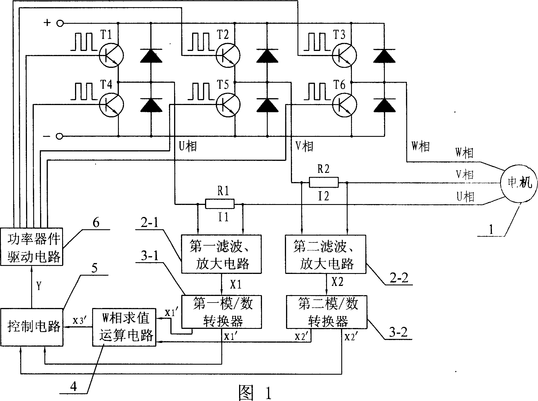
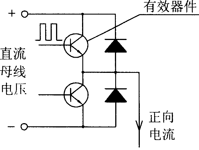
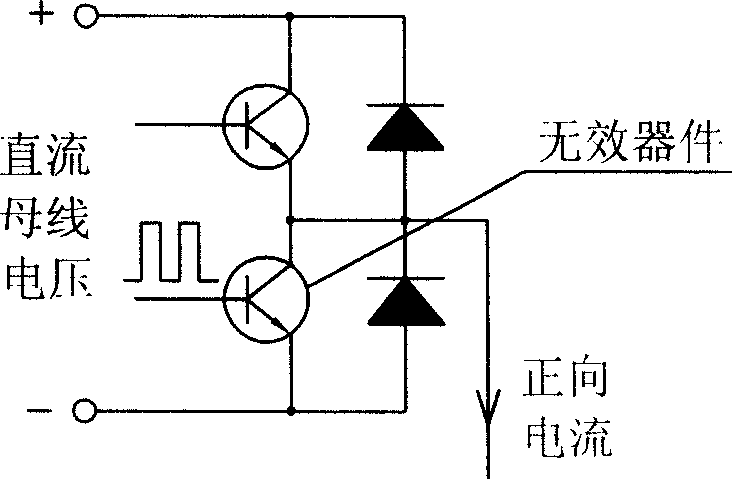
[0005] Combining Figure 1 and Figure 6 This method will be specifically described. It is realized through the following steps: 1. Use the first current detection resistor R1 and the second current detection resistor R2 connected in series in the U-phase winding and V-phase winding loops of the motor 1 to respectively detect the U-phase current signal I1 and V-phase current signal I2; 2. Filter and amplify the U-phase current signal I1 and V-phase current signal I2 respectively through the first filtering and amplifying circuit 2-1 and the second filtering and amplifying circuit 2-2 to obtain the first analog quantity One signal X1, the second signal X2 of the analog quantity; Three, respectively use the first analog / digital converter 3-1 and the second analog / digital converter 3-2 to convert the first signal X1 of the analog quantity, the second signal X1 of the analog quantity The second signal X2 is converted into the first signal X1' of the digital quantity and the second...
PUM
 Abstract
Description
Claims
Application Information
 - R&D
- Intellectual Property
- Life Sciences
- Materials
- Tech Scout
- Unparalleled Data Quality
- Higher Quality Content
- 60% Fewer Hallucinations
Browse by: Latest US Patents, China's latest patents, Technical Efficacy Thesaurus, Application Domain, Technology Topic, Popular Technical Reports.
© 2025 PatSnap. All rights reserved.Legal|Privacy policy|Modern Slavery Act Transparency Statement|Sitemap|About US| Contact US: help@patsnap.com


