Light roughcast mould assembly for on site pouring reinforced concrete filling

A reinforced concrete, lightweight technology, applied in building components, floors, buildings, etc., can solve the problems of the number of formwork, specifications, lengthened construction period, complex construction, etc., to achieve simple mold, reduce production and construction costs, construction simple effect

Inactive Publication Date: 2006-02-22
湖南邱则有专利战略策划有限公司
View PDF1 Cites 0 Cited by
  • Summary
  • Abstract
  • Description
  • Claims
  • Application Information

AI Technical Summary

Problems solved by technology

However, the construction of this kind of reinforced concrete shear key type two-way hollow slab is complicated, troublesome, and takes a long period of time. It is necessary to first construct the cast-in-place lower ribs. , and then put the prefabricated upper formwork, which will inevitably lengthen the construction period. Generally, the construction period is twice as long as that of the beam-slab structure, especially the number and specifications of the formwork are large, so the construction is complicated and troublesome. Expense is high, therefore, aiming at above-mentioned deficiency, develop a kind of new-type cast-in-place reinforced concrete filling lightweight tire mold assembly has been urgently needed

Method used


Image

  • Light roughcast mould assembly for on site pouring reinforced concrete filling
  • Light roughcast mould assembly for on site pouring reinforced concrete filling
  • Light roughcast mould assembly for on site pouring reinforced concrete filling

Examples


Embodiment Construction

[0050] The present invention will be further described below in conjunction with drawings and embodiments.

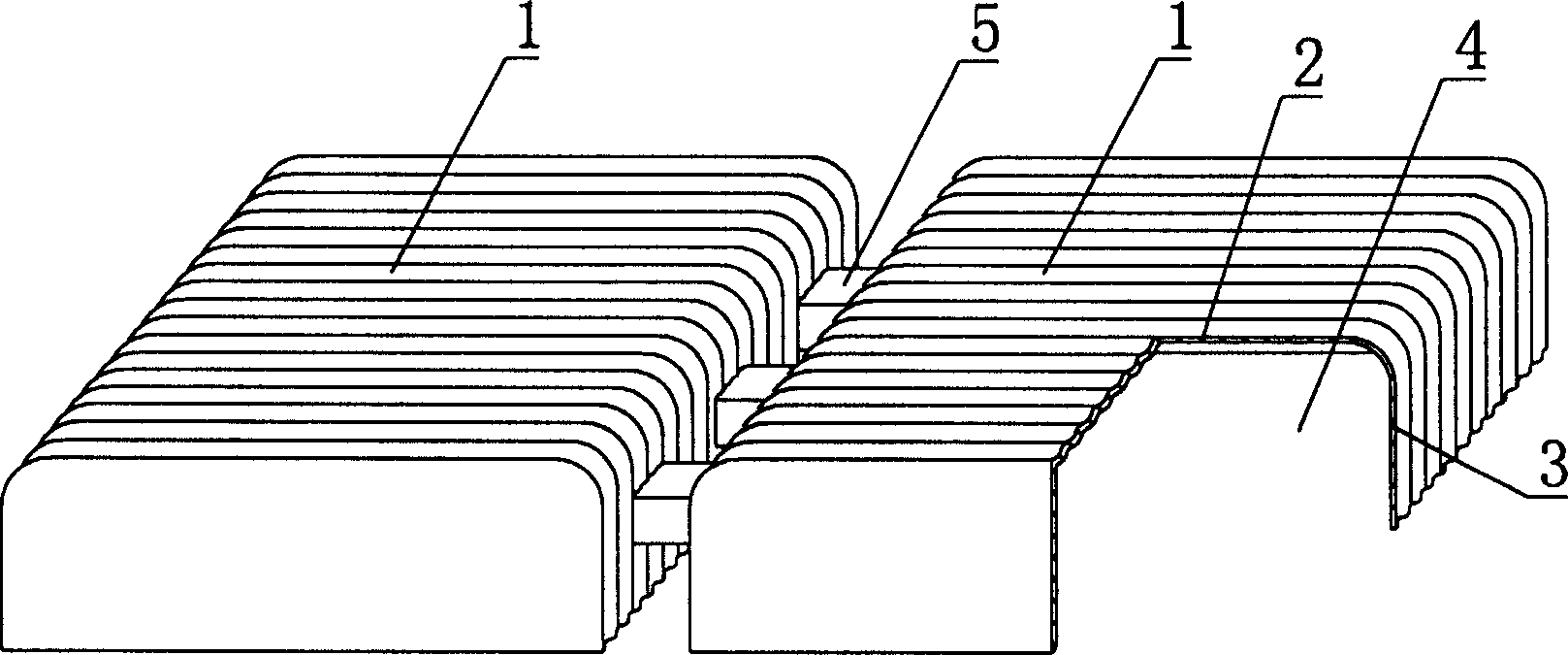
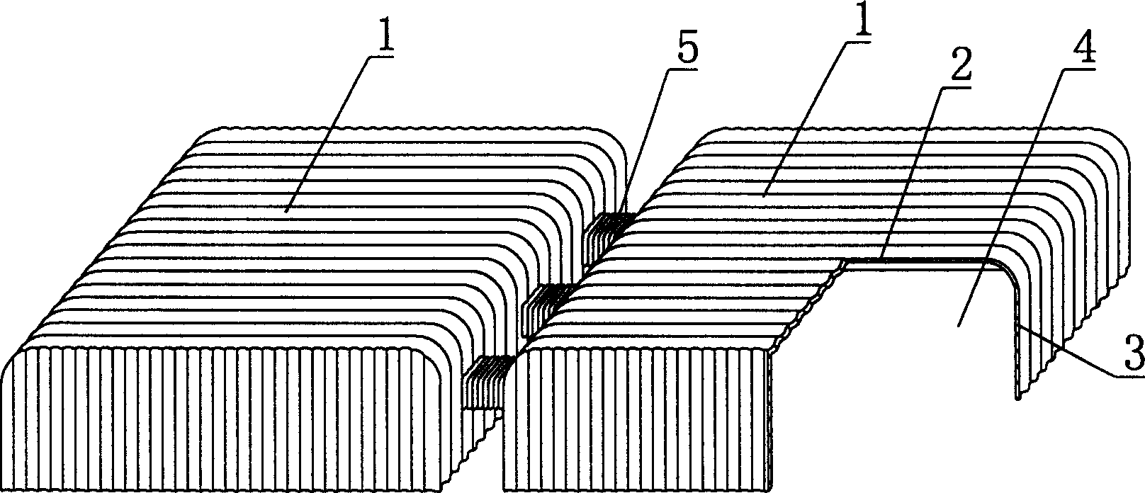
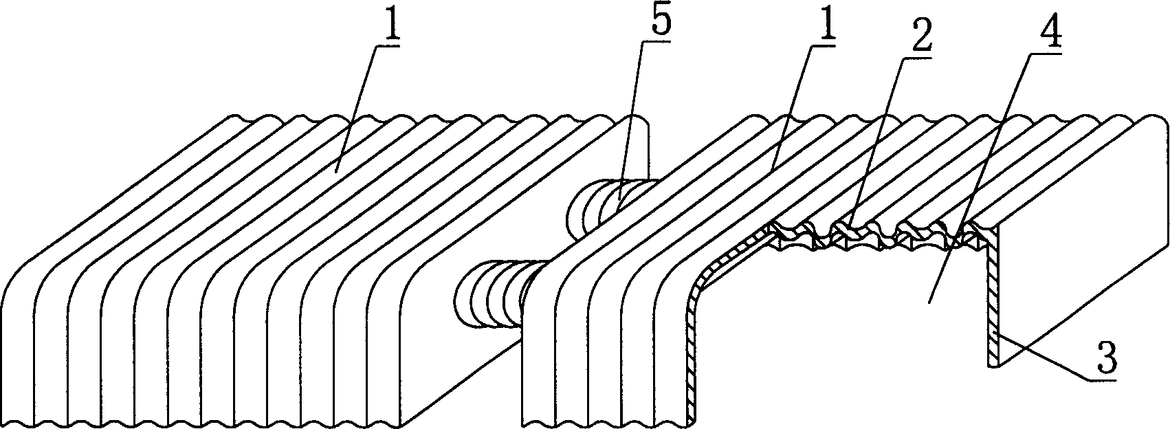
[0051] As shown in the drawings, the present invention includes a carcass 1, which is formed by an open cavity 4 surrounded by an upper plate 2 and a side wall 3, and is characterized in that the carcass 1 is an open corrugated carcass, at least two The open corrugated carcass 1 has a connecting pipe 5 on at least one place of the side wall 3 to connect the open corrugated carcass 1 together, and the connecting pipe 5 is a corrugated connecting pipe. figure 1 It is a structural schematic diagram of Embodiment 1 of the present invention. figure 1 As shown, 1 is the corrugated carcass, 2 is the upper plate of the corrugated carcass 1, 3 is the side wall of the corrugated carcass 1, 4 is the cavity surrounded by the upper plate 2 and the side wall 3, and 5 is the connecting pipe. In the accompanying drawings, those with the same number have the same description. Such as ...


PUM


Abstract

A light filler module for in-situ casting the hollow concrete floor, roof, wall and foundation is a corrugated cavity composed of top plate and side plates. The connecting tubes are connected between the side walls of two adjacent filler modules to form the ribs and shear bonds in the in-situ cast hollow slab. Its advantages are high strength, simple structure and low cost.

Description

(1) Technical field [0001] The invention relates to a lightweight tire mold assembly for filling cast-in-place reinforced concrete. (2) Background technology [0002] At present, the building (roof) structure is the most widely used cast-in-place concrete hollow structure. The common structural forms include beam-slab or ribbed floor, prestressed slab structure, and non-prestressed slab structure. These structures have their own characteristics. Insurmountable shortcomings. In general, the height of the beam-slab floor structure needs to be 1 / 10-1 / 12 of the span of the frame beam section, so the structure takes up a lot of space, which is not convenient for the pipeline layout in the building. Take up interior space. In order to meet the requirements of indoor space, the height of the storey must be increased in the structure. When the height of the storey is limited, only wide flat beams no larger than the column width can be used to meet the rigidity requirements. At thi...

Claims


Application Information

Patent Timeline
Patent Type & Authority Patents(China)
IPC IPC(8): E04B5/36
Inventor 邱则有
Owner 湖南邱则有专利战略策划有限公司
Why Eureka
Try Eureka