
Device for mixing fluid

A technology for mixing fluids and fluids, which is applied in the direction of mixers, fluid mixers, gas and gas/steam mixing, etc. It can solve the problems of nozzle fuel cell function loss, nozzle clogging, nozzle efficiency reduction, etc., and improve operational safety. and reliability effects

Inactive Publication Date: 2006-03-22
ROBERT BOSCH GMBH
View PDF0 Cites 0 Cited by
  • Summary
  • Abstract
  • Description
  • Claims
  • Application Information

AI Technical Summary

Problems solved by technology

[0003] In this case, the problem arises several times: the supplied water vapor condenses in the nozzle or in the nozzle valve, which leads to condensation and thus to clogging of the nozzle, or to a loss of function of the nozzle and the downstream fuel cell ; or lead to a significant reduction in the efficiency of the nozzle

Method used


Image

  • Device for mixing fluid
  • Device for mixing fluid
  • Device for mixing fluid

Examples


Embodiment Construction

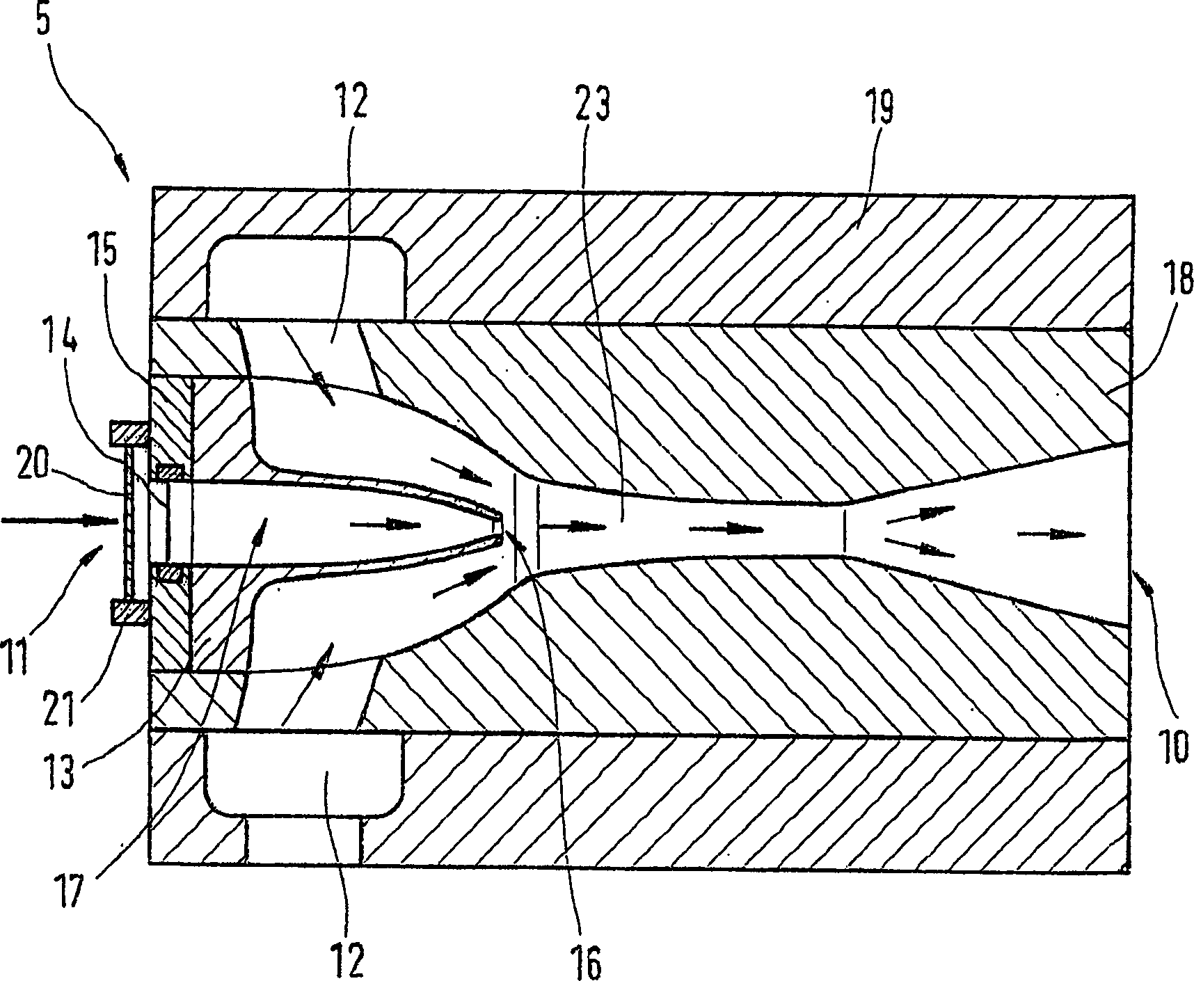
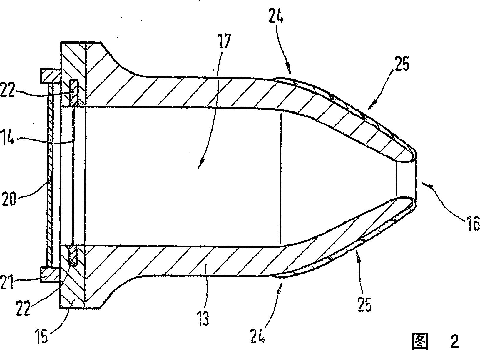
[0020] figure 1 A fluid mixing device 5 acting as a gas injection valve or mixing nozzle is shown. The fluid mixing device 5 is in particular a jet compressor nozzle, through which a strong, driving fluid carries a second, weaker fluid. For example, in the fluid mixing device 5 described, hydrogen and saturated water vapor are mixed with each other in a mixing tube or in a mixing zone inside the mixing device.

[0021] The fluid mixing device 5 additionally has a base body 18 which is surrounded by a sleeve 19 having an annular groove through which the first fluid, for example hydrogen or a gas containing hydrogen, can be supplied to the base body 18 . Furthermore, a funnel-shaped recess is provided in the base body 18 , which opens into a central duct 23 , which leads into a funnel-shaped opening 10 of the fluid mixing device 5 . Sleeve 19 or base body 18 according to figure 1 Preferably designed as a cylindrically symmetrical structure.

[0022] figure 1 Also shown, for...


PUM


Abstract

Disclosed is a device for mixing fluids, especially a gas injection valve, a nozzle valve, a mixing valve or a jet compressor. A first fluid guiding device (12) is provided in order to guide a first fluid and a second fluid guiding device (13) is provided in order to guide a second fluid. The fluids are mixed with each other in a mixing area (16) which is connected to the fluid guiding devices (12,13). At least one of the fluid guiding devices (12, 13) is provided with a means (20) for producing turbulence in the related fluid, and a heating device which is associated with said means (20) and which in relation to the direction of flow of said fluid is disposed downstream therefrom. Said heating device is used to heat the fluid before it reaches the mixing area (16). The inventive device is especially used to mix hydrogen and saturated water vapour and is used to feed said mixture to a fuel cell.

Description

technical field [0001] The invention relates to a device for mixing fluids, in particular a gas injection valve, a mixing nozzle or a jet compressor nozzle, for example for fuel supply in a fuel cell. Background technique [0002] It is known that during the operation of fuel cells, a mixture of hydrogen and saturated water vapor is supplied to the fuel cells, the amount and composition of the mixture of hydrogen and saturated water vapor being dosed or regulated via a nozzle valve. [0003] In this case, the problem arises several times: the supplied water vapor condenses in the nozzle or in the nozzle valve, which leads to condensation and thus to clogging of the nozzle, or to a loss of function of the nozzle and the downstream fuel cell ; or lead to a significant reduction in the efficiency of the nozzle. Contents of the invention [0004] The object of the present invention is to provide a device for mixing fluids, in particular hydrogen and in particular saturated wa...

Claims


Application Information

Patent Timeline
Patent Type & Authority Patents(China)
IPC IPC(8): B01F5/04B01F15/06F23D14/64H01M8/04B65B57/02B01F23/10B65B57/18B67B1/00B67B3/26F23D11/40F23D11/44F23D14/66F23M5/02G06T1/00H01M8/04007H01M8/04089H01M8/04119
CPCH01M8/04089B01F5/0413B01F5/0428B01F5/0473B01F15/066B01F2005/0025B01F2005/0048B01F2015/062F23D11/402F23D11/44F23D14/64F23D14/66F23M5/025H01M8/04007H01M8/04119Y02E60/50Y02E20/34B01F2025/916B01F2025/919121B01F25/31242B01F25/3141B01F25/312B01F35/93B01F2035/99
Inventor I·法耶T·-H·阮-谢菲尔
Owner ROBERT BOSCH GMBH
Learn More