
Continuous processing system for steel strip
A processing system and technology for steel strips, applied in the field of continuous processing systems for steel strips, to achieve the effect of high strip speed and high productivity
- Summary
- Abstract
- Description
- Claims
- Application Information
AI Technical Summary
Problems solved by technology
Method used
Image

Examples
Embodiment Construction
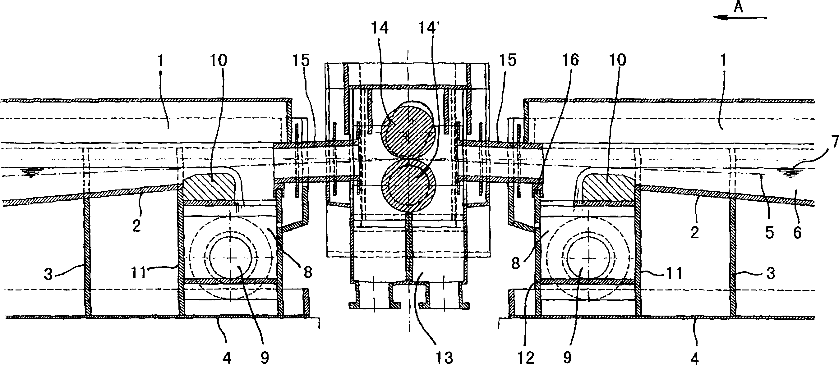
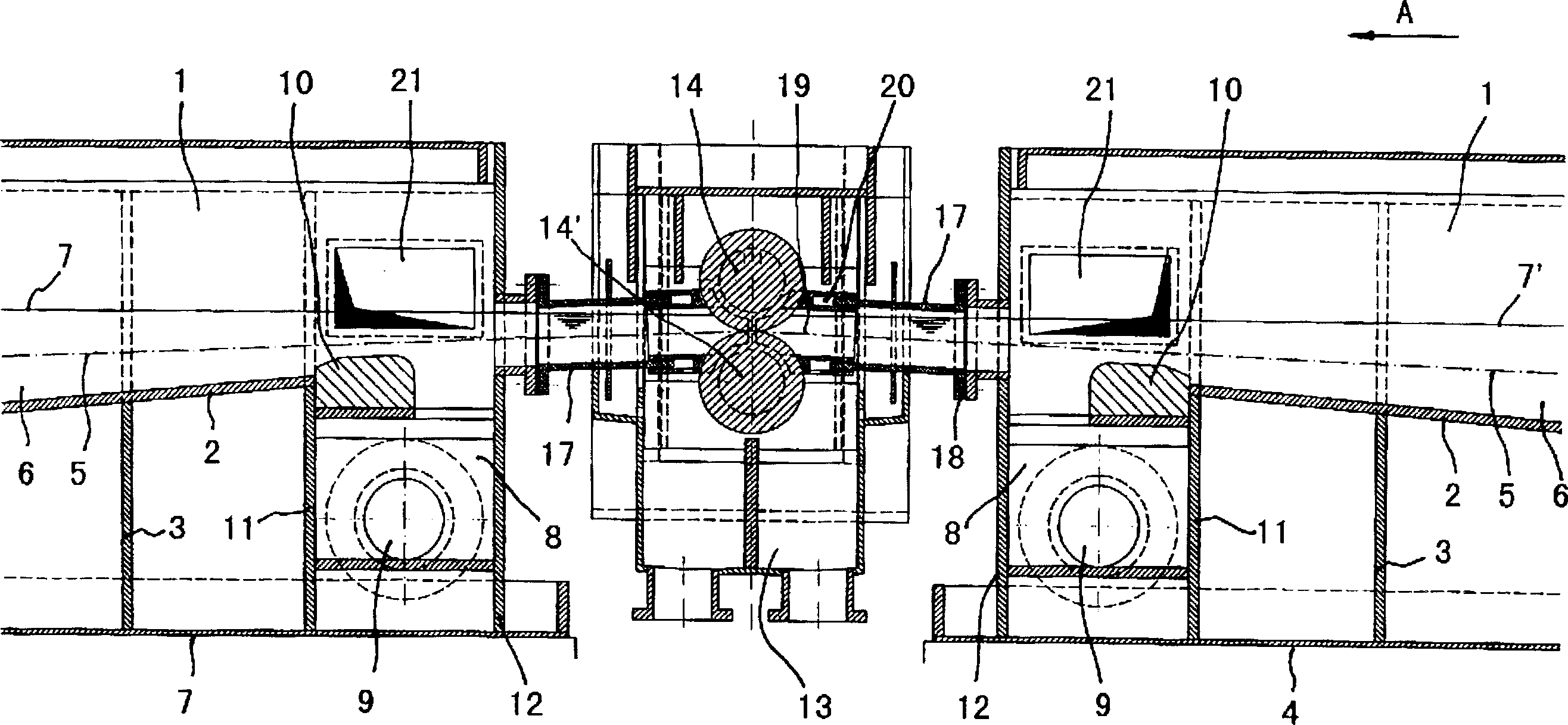
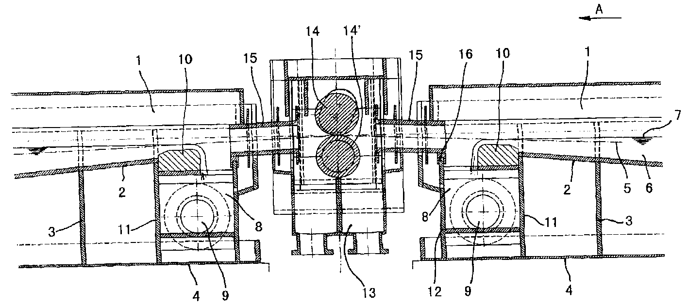
[0015] figure 1 A pickling tank 1 is shown, the bottom 2 of which is supported on a tray 4 with pillars 3 without seams. The steel strip 5 moves in the direction A in the processing liquid 6 with a liquid level of 7. At the end of the treatment tank 1 is provided an outlet tank 8 into which the liquid flows and is discharged through a laterally arranged discharge pipe 9. In order to better adjust the liquid level 7, a protective belt 10 that can best be drawn out is provided. The protective belt 10 is designed such that the steel belt 5 is slightly higher than the wall 11 of the outlet groove 8 when exposed from the liquid. Due to the expansion, the opposite wall 12 can move in the direction of arrow D within the disk 4.
[0016] The groove 13 for accommodating the press rolls 14, 14' is arranged separately from the groove 1. The top of this trough can be closed. At the other end of the treatment tank 1 is provided a tank 13 of the same type with press rolls 14, 14'. The connect...
PUM
 Abstract
Description
Claims
Application Information