Filter sand washing method and its system

A technology for filtering sand and cleaning water, which is applied in the field of sand cleaning to achieve the effect of prolonging the time period.

Inactive Publication Date: 2006-08-23
NIHON GENRYO CO LTD
View PDF0 Cites 2 Cited by
  • Summary
  • Abstract
  • Description
  • Claims
  • Application Information

AI Technical Summary

Problems solved by technology

Therefore, these conditions lead to the regeneration process having to be performed more quickly
Therefore, it is considered that there are limitations, that is, the extent to which traditional surface cleaning and backwash cleaning can handle the contamination of the filter media

Method used

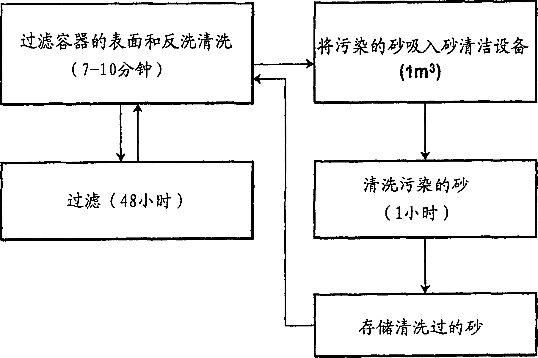
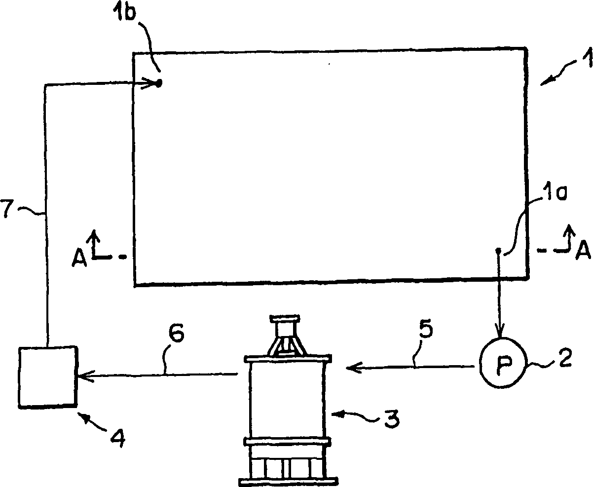
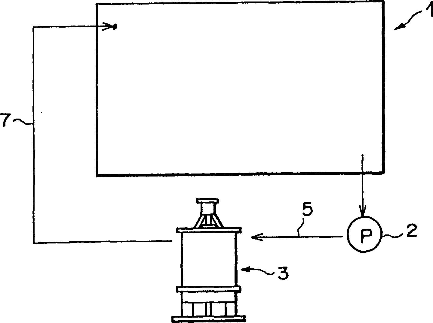

Image

  • Filter sand washing method and its system
  • Filter sand washing method and its system
  • Filter sand washing method and its system

Examples


Embodiment 1

[0066] A sand washing apparatus disclosed in Japanese Unexamined Patent Publication No. Hei10-109051 comprises: a washing tank for containing sand and washing water therein; a Rotating auger; a rotating mechanism for rotating the auger at such a speed that, at the lower portion of the auger below the surface of the wash water, the rotation of the auger causes sand and cleaning water is raised while removing contaminants from the sand by contact between the sand particles and the cleaning water therebetween, and the rotation of the screw conveyor causes the sand to flow while passing a small amount of load between the sand particles and between them. Contaminants are removed from the sand by contact with contaminated water; a circulation mechanism is used as a sand washing device 3, which is used to cause the raised sand to be lowered to the lower part of the screw conveyor, and thereby to regenerate the sand Raised, thereby realizing the friction cleaning method. Such as fig...

Embodiment 2

[0070] Cleaning of filter sand was performed in the same manner as in Embodiment 1 above, except that a conventional water-jet sand cleaning device was used instead of the specific sand cleaning device. As shown in Table 4, although there was a slight difference between Example 1 and Example 2 using the specific sand cleaning equipment, the contaminated sand was significantly cleaned. In the case of Example 1, there was hardly any change in the effective particle diameter. However, in Example 2, since the cleaning was performed for a long time, the effective particle diameter decreased and the uniformity coefficient increased. It should be understood that in a conventional sand cleaning device using water jets, the sand collides with pipes, walls, etc. during cleaning, resulting in damage to the pipes, walls, etc.

[0071] polluted sand

After cleaning (minutes)

10

20

30

60

Pollution (degree)

Hydrochloric acid solubility

...


PUM


Abstract

When backwashing a rapid filter where water is washed with filter sand, a preset amount of filter sand is sucked from the rapid filter by a pump. The sucked filter sand is fed to a sand washing device where the contaminants on the filter sand are removed. Contaminats-removed filter sand is kept in a washed-sand stock tank, and stored filter sand is returned to the rapid filter when the rapid filter is backwashed. An automatic washing of filter sand in the rapid filter is possible by repeating the steps of sucking, washing and returning filter sand, whereby a sand washing function is regenerated by a washing method other than surface washing and backwashing to thereby drastically prolong a regenerating cycle of a filter pond.

Description

technical field [0001] The invention relates to a method of washing filter sand from a filter vessel for filtering water and to a system for the method. More particularly, the present invention relates to a method for cleaning a portion of filter media removed from a high velocity filter vessel and to a system for such method. Background technique [0002] The water purification process in water treatment plants involves the addition of chemicals to untreated water drawn from rivers, lakes, ponds or wells to solidify suspended matter to a size that causes the solidified matter to settle to the bottom. The supernatant is skimmed and sent to a filter vessel where it is passed through a layer of sand (filter sand) to remove finer suspended matter. The water is then disinfected with chlorine. In high-speed filter vessels, the filter media is periodically cleaned at 24-72 hour intervals. As methods for cleaning the filter media, there are: surface cleaning, in which water is s...

Claims


Application Information

Patent Timeline
IPC IPC(8): B01D41/02B01D24/00
CPCB01D24/4631
Inventor 斋藤安弘
Owner NIHON GENRYO CO LTD
Why Eureka
Try Eureka