Apparatus and method for writing curve servo sector image

A sector and curve technology, applied in the field of media master production, which can solve problems such as output and multiple memory

Inactive Publication Date: 2006-10-11
SEAGATE TECH LLC
View PDF0 Cites 0 Cited by
  • Summary
  • Abstract
  • Description
  • Claims
  • Application Information

AI Technical Summary

Problems solved by technology

This requires more memory

Method used


Image

  • Apparatus and method for writing curve servo sector image
  • Apparatus and method for writing curve servo sector image
  • Apparatus and method for writing curve servo sector image

Examples


Embodiment Construction

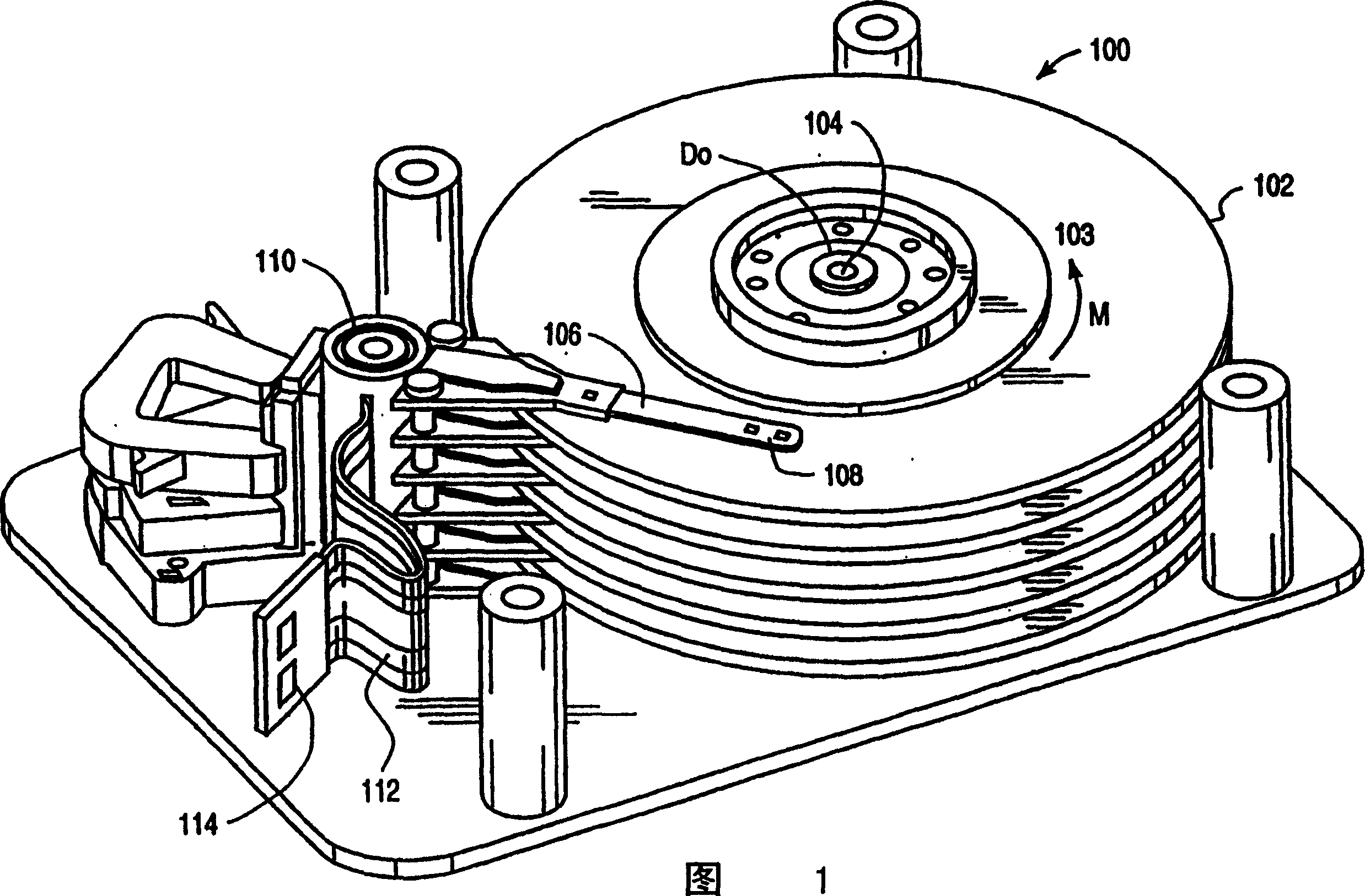
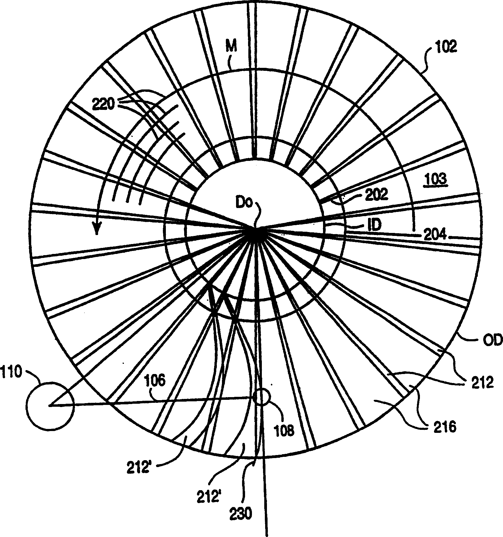
[0030] Referring now to the block diagram in FIG. 1 , an exemplary data storage disk system 100 includes a plurality of disks 102 mounted on a drive spindle 104 extending through a central hole D in the disks. 0 . Disk 102 rotates in a counterclockwise direction (as indicated by arrow M) at a speed measured in revolutions per minute. An actuator arm 106 at one end carries a suspended read / write head 108 over the surface 103 of a selected disk 102 . Although the read-write head 108 is shown positioned above the upper surface of the uppermost disk in the stack, it should be understood that the read-write head 108 may also reside on the upper and lower surfaces of any number of disks 102 . The opposite end of the actuator arm 106 is connected to a rotary actuator assembly 110 configured to rotate the actuator arm 106 so that the read / write head 108 pivots. The data pulse signal is received from the associated disk surface 103 and transmitted in a conventional manner along the a...


PUM


Abstract

Curve servo is generated on a master medium by determining a series of offsets between the radial alignment reference and the desired curve servo sector, and expressing each offset as a set delay for master writer control sector chart. Incorporating delays into the master writer allows data mapping to be employed to generate curved servo sector patterns. In this way, a curved servo sector pattern with desired resolution is produced without increasing computational overhead or increasing memory requirements, or reducing yield. The delay may be transformed into control settings such as sector delay, clock cycle delay, and residual fractional delay settings each representing a fraction of the delay. In some embodiments, a piecewise linear approximation of the curve shape can be implemented to reduce the amount of control data required, and a master write controller that generates multiple laser pulses can be implemented.

Description

[0001] This application is a divisional application of the domestic phase invention patent application 99805831.9 of the PCT application filed on May 10, 1999. technical field [0002] This invention relates generally to the production of media masters and, more particularly, to the writing of curved servo sector patterns on media masters. Background technique [0003] Many data storage disk systems incorporate actuator arms that carry read and write heads above the surface of the disk. The actuating arm is connected to an actuating assembly, so that the actuating arm rotates around the pivot axis. This causes the read / write head to travel along an arc of a circle centered on the pivot axis with a radius determined by the length of the actuator arm. [0004] During operation, the rotation of the platter and the movement of the head give the position of the head relative to the surface of the disk. A typical disc includes a number of servo sectors grouped together to form a...

Claims


Application Information

Patent Timeline
IPC IPC(8): G11B20/10G11B5/09G11B5/84G11B5/596G11B21/10G11B23/00
CPCG11B5/59633G11B21/10G11B23/0042G11B23/0085
Inventor S·J·哈林亚K·A·贝塞尔
Owner SEAGATE TECH LLC
Why Eureka
Try Eureka