

Plasma display structure
A plasma and display technology, applied in the direction of solid cathode components, cold cathode tubes, etc., can solve problems such as limited luminous brightness, interference of display units, and affecting the display quality of plasma displays 10, so as to achieve good brightness, reduce interference, and improve The effect of the space discharge effect
- Summary
- Abstract
- Description
- Claims
- Application Information
AI Technical Summary
Problems solved by technology
Method used
Image

Examples
no. 1 example
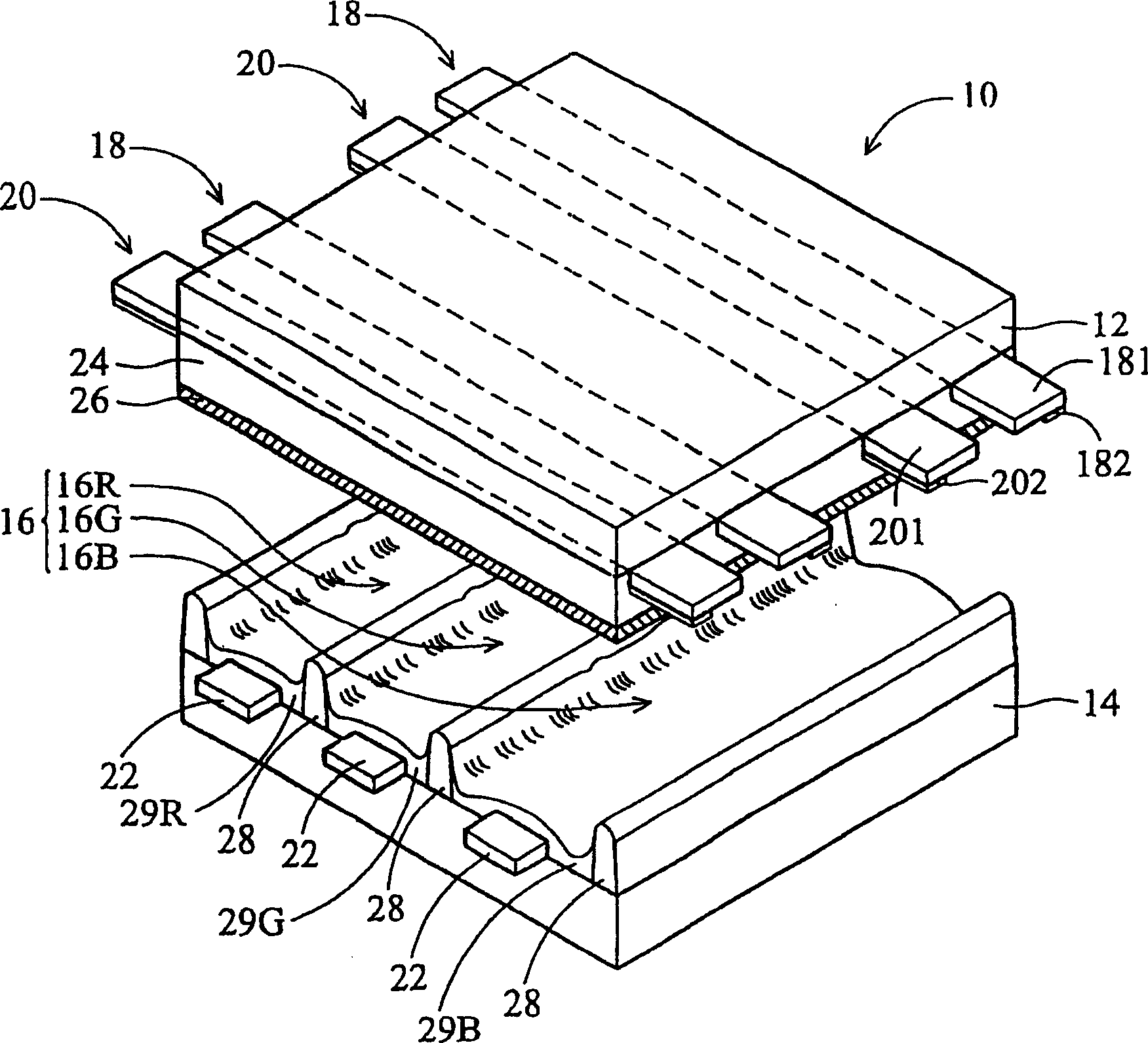
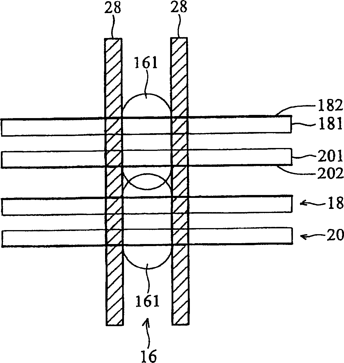
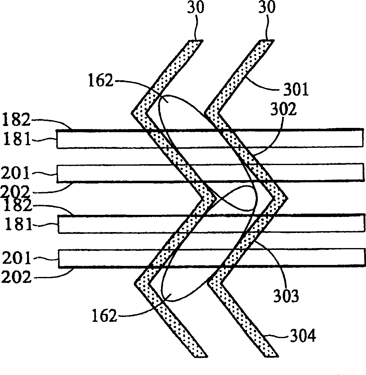
[0044] First see image 3 , which shows a partial top view of the structure of the plasma display in the first embodiment of the present invention. As shown in the figure, the present invention improves the structure of the existing plasma display, in which the extension electrodes 181 and 201 and the elongated auxiliary electrodes 182 and 202 are disposed on the upper glass substrate 12 , which is different from the existing plasma display 10 . Yes, in the present invention, a plurality of tortuous barrier walls 30 are provided on the lower glass substrate 14 .
[0045] like image 3 As shown, wherein the above-mentioned blocking wall 30 is composed of a plurality of straight line segments, including a first straight line segment 301, a second straight line segment 302, a third straight line segment 303 and a fourth straight line segment 304 that are arbitrarily connected; Two adjacent straight line segments have an included angle greater than 0 degree and less than 180 deg...
no. 2 example
[0050] Then see Figure 4 , which shows a partial top view of the plasma display structure in the second embodiment of the present invention. like Figure 4 As shown, wherein the above-mentioned blocking wall 30 is composed of a plurality of straight line segments, including a first straight line segment 301, a second straight line segment 302, a third straight line segment 303 and a fourth straight line segment 304 that are arbitrarily connected; Two adjacent straight line segments have an included angle greater than 0 degree and less than 180 degrees; that is, the two adjacent straight line segments are connected but not parallel.
[0051] In addition, the spaced first straight line segment 301 and the third straight line segment 303, and the second straight line segment 302 and the fourth straight line segment 304 are parallel to each other. In addition, the above-mentioned plurality of blocking walls 30 are disposed on the lower glass substrate 14 in parallel.
[0052] ...
no. 3 example
[0054] Then see Figure 5 , which shows a partial top view of the plasma display structure in the third embodiment of the present invention. Different from the above-mentioned first and second embodiments, in this embodiment, the laterally extending auxiliary electrodes 182 are in a shared form, wherein each auxiliary electrode 182 is connected to a laterally extending electrode 184 respectively.
[0055] like Figure 5 As shown, wherein the above-mentioned blocking wall 30 is composed of a plurality of straight line segments, including a first straight line segment 301, a second straight line segment 302, a third straight line segment 303 and a fourth straight line segment 304 that are arbitrarily connected; Two adjacent straight line segments have an included angle greater than 0 degree and less than 180 degrees; that is, the two adjacent straight line segments are connected but not parallel.
[0056] In addition, the spaced first straight line segment 301 and the third st...
PUM
 Abstract
Description
Claims
Application Information