

Magnetoelectric tube device and its production method
A magnetron, tubular technology, applied in the field of magnetron devices, can solve the problem of reducing the performance of anti-noise
- Summary
- Abstract
- Description
- Claims
- Application Information
AI Technical Summary
Problems solved by technology
Method used
Image

Examples
no. 1 example
[0047] (Structure of magnetron device)
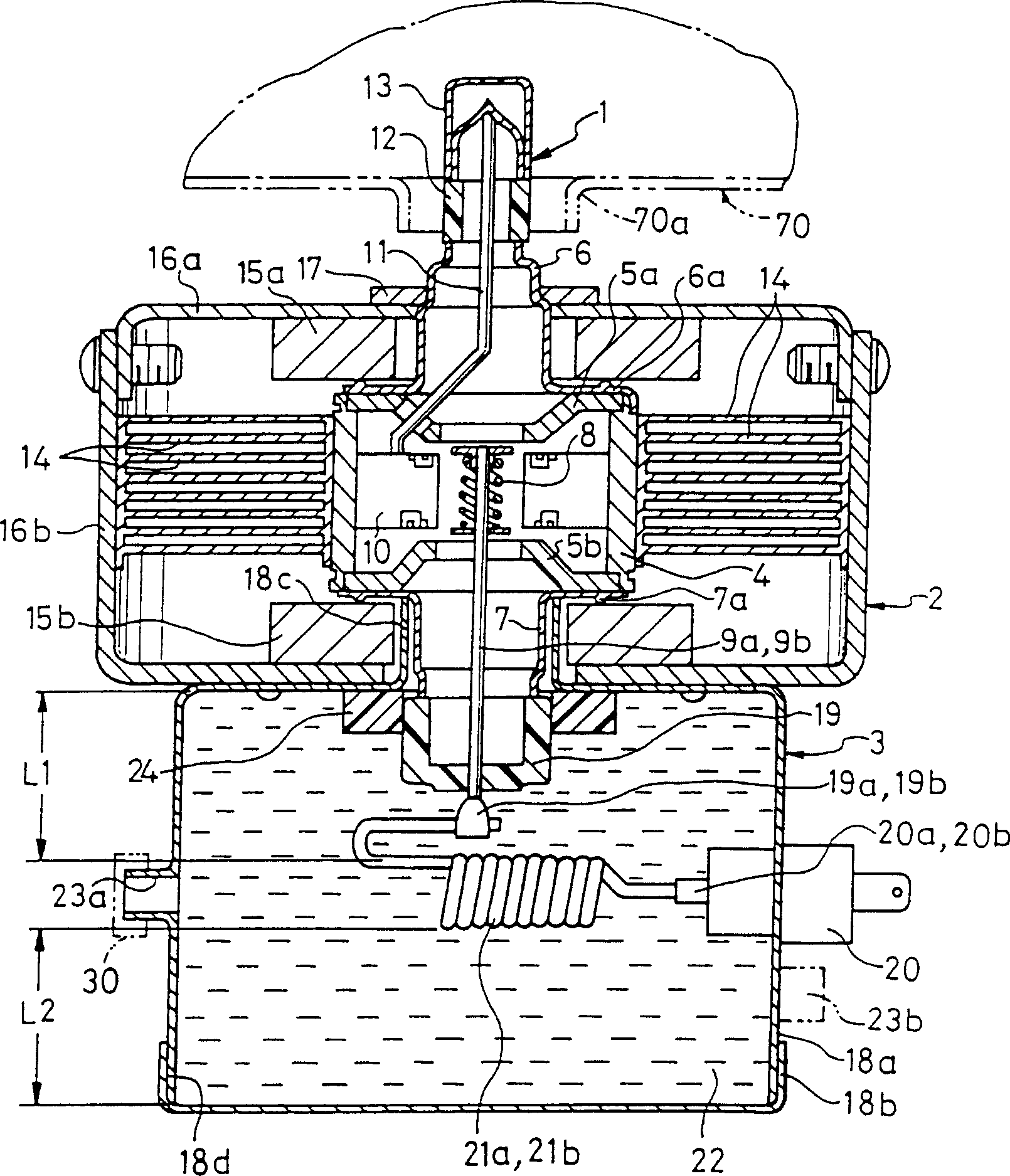
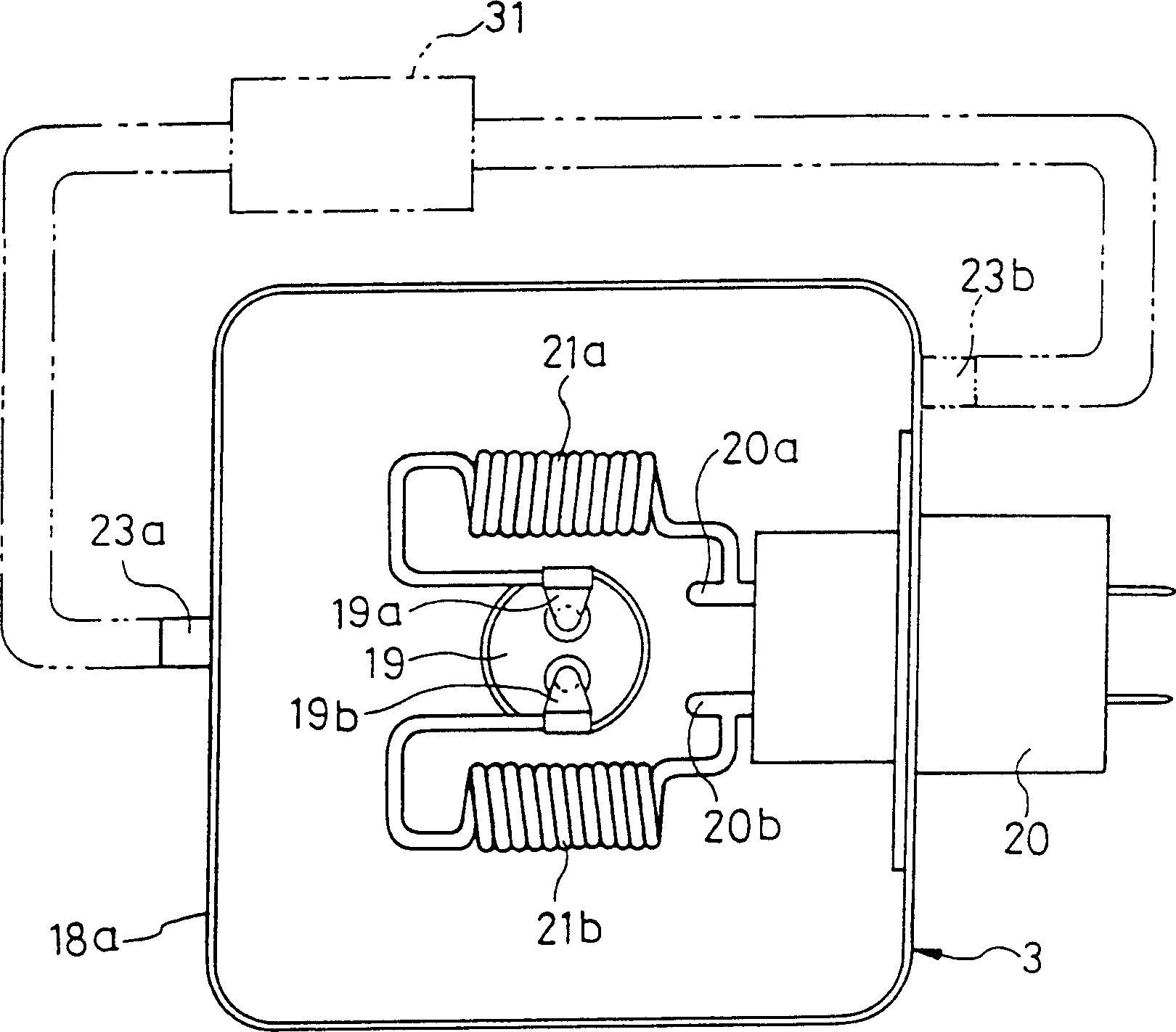
[0048] figure 1 is a sectional view showing the structure of the magnetron device in the first embodiment of the present invention, figure 2 is a bottom view, which shows the figure 1 The bottom structure of the magnetron device shown.
[0049] Such as figure 1 and 2 As shown, the magnetron of the present invention includes a magnetron part 1, a magnetic circuit part 2 that excites the magnetron part 1, and a radio wave leakage prevention device with an LC filter line element to prevent high frequency noise leakage Part 3.
[0050] The magnetron part 1 includes a tubular anode 4, first and second magnetic pole parts 5a and 5b respectively provided at upper and lower opening portions of the tubular anode 4, and grommets respectively provided in the first and second magnetic pole parts 5a and 5b. Grommetted first and second metal tubes 6 and 7. The outer end surface of the first pole piece 5a is covered with a flange portion 6a...
no. 2 example
[0076] Figure 4 is a sectional view showing the structure of a magnetron device according to a second embodiment of the present invention. Figure 5 is a stereogram showing Figure 4 The structure of the magnetron device shown. In this embodiment, the magnetron device is constructed such that the magnetic circuit part is disposed in the filter housing of the radio wave leakage preventing part, whereby the tubular anode, first and second magnets and blades are directly cooled by the insulating cooling liquid. Since other parts are the same as those of the first embodiment, their explanations are omitted to avoid repetition.
[0077] Such as Figure 4 As shown, the magnetic circuit part 2 of the magnetron device of this embodiment is surrounded and accommodated by filter case parts 25a and 25b of a radio wave leakage preventing part 3'. As a result, when filter housing members 25a and 25b internal spaces are equipped with such Figure 4 When the insulating cooling liquid 2...
no. 3 example
[0087] Figure 6 is a sectional view showing the structure of a magnetron device according to a third embodiment of the present invention. Figure 7 is a stereogram that shows Figure 6 The structure of the magnetron device shown. In the structure of the magnetron device of this embodiment, the yoke is a part of the filter case. Since other parts are the same as those of the first embodiment, their explanations are omitted to avoid repetition.
[0088] Such as Figure 7 As shown, in the magnetron device of the present embodiment, the tubular anode 4, the first and second magnets 15a and 15b, etc. are surrounded by filter housing members 27a and In the inner space of 27c. Thus, a magnetic circuit part 2' is formed. The high voltage capacitor 20 and the throttle coils 21a and 21b are arranged in a space enclosed by the filter housing members 27b and 27c. In addition, the inner spaces of the filter housing members 27a and 27b are sealed so that the insulating cooling liqui...
PUM
 Abstract
Description
Claims
Application Information