Peripheral rewinding machine for producting rolls of wound web material and corresponding method of winding

A technology of rewinding machine and roll production, which is applied in the directions of winding strips, thin material handling, transportation and packaging, etc., and can solve problems such as web deformation

Inactive Publication Date: 2001-04-11
FABIO PERINI SPA
View PDF5 Cites 9 Cited by
  • Summary
  • Abstract
  • Description
  • Claims
  • Application Information

AI Technical Summary

Problems solved by technology

The disadvantage of this type of machine is that a very large retraction force is required to overcome the frictional force when withdrawing the rela

Method used


Image

  • Peripheral rewinding machine for producting rolls of wound web material and corresponding method of winding
  • Peripheral rewinding machine for producting rolls of wound web material and corresponding method of winding
  • Peripheral rewinding machine for producting rolls of wound web material and corresponding method of winding

Examples


Embodiment Construction

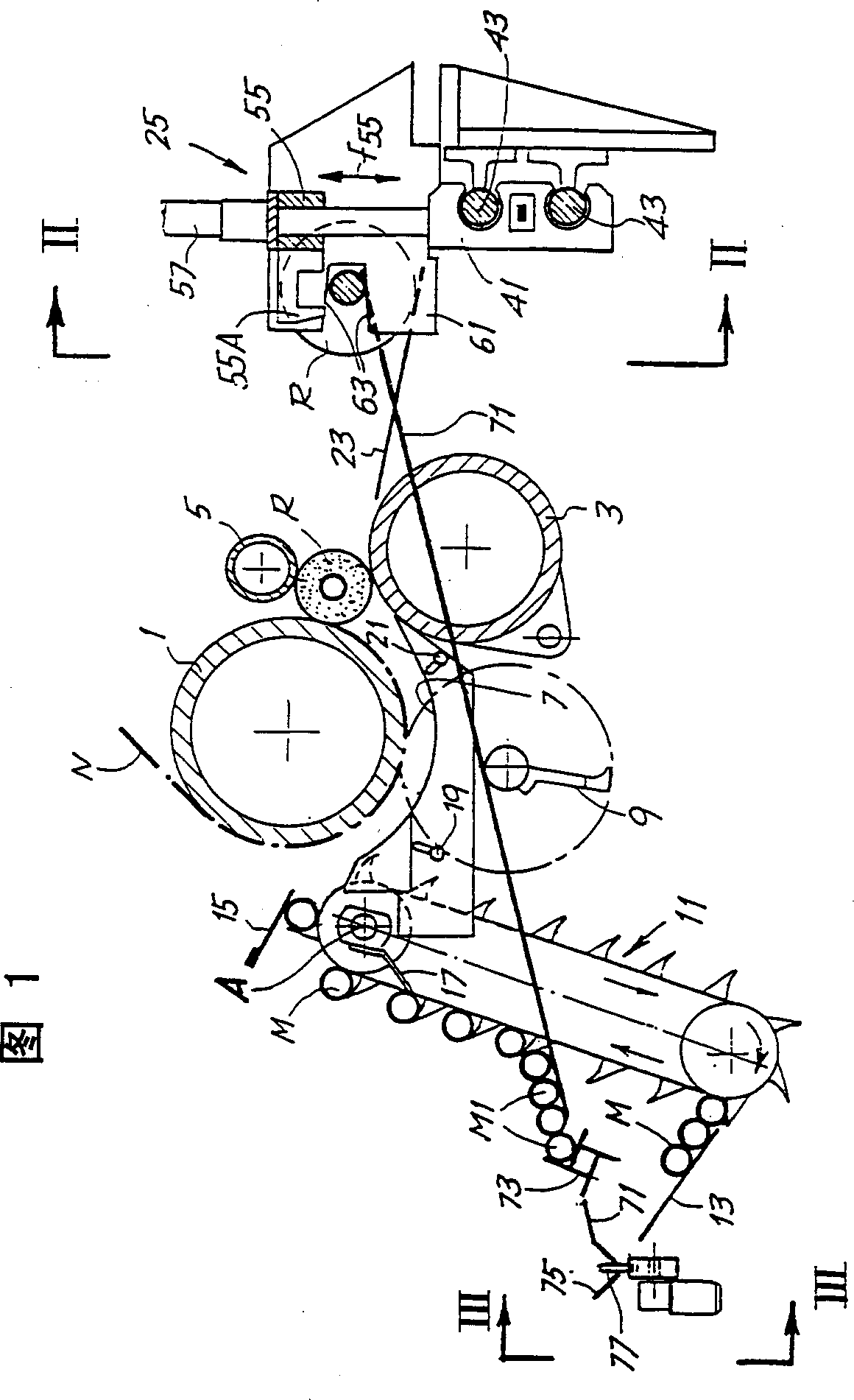
[0023] In the following description, it is illustrated that the present invention is applied to an automatic peripheral rewinding machine described in WO-A-9421545, but it is understood that the concept of the present invention can also be applied to automatic peripheral rewinding with other configurations machine.

[0024] Figure 1 schematically shows the winding area of ​​a peripheral winding machine. The letter N designates a web to be wound, such as a single or multiple sheets of paper to be wound into a roll, with transverse perforations, if required. Reference numerals 1, 3 and 5 denote 3 winding rollers which define a winding area forming the roll R. As shown in FIG. The web N runs around the upper winding roll 1 and the reel R is formed in the area between the rolls 1, 3 and 5 and is in contact with them.

[0025] An insertion channel for the winding mandrel M is formed by a curved surface 7 located below the winding roller 1 . A rotating system 9 , which is locat...


PUM


Abstract

The rewinding machine comprises: an insertion device (11) for sequentially inserting winding spindles (M) into a winding area; winding means (1, 3, 5) in said winding area, which wind predetermined quantities of web material onto said spindles; an extractor (25) for extracting said spindles from the rolls of web material formed on them; and a recirculation path (71) for returning the spindles extra from said rolls toward said insertion device. The spindles are made in two portions which can be connected and disconnected; the extractor extracts each of said two portions from a corresponding end of the corresponding wound roll. Means are also provided for reconnecting said two portions to each other so that said spindles can be reinserted into said winding area.

Description

technical field [0001] The invention relates to a peripheral rewinding machine for producing rolls of web material (Web material, also known as roll material, roll paper in the paper industry), the rewinding machine includes: insertion means for inserting the mandrel sequentially into the winding area; winding means for winding a predetermined amount of web on the mandrel in said winding area; withdrawal means for removing the web from the web formed on the mandrel a reel exiting the mandrel; and recirculation means for returning the mandrel exiting the reel to the insertion device. [0002] The mandrel is driven in rotation by the winding device or initially by a suitable element acting on the mandrel independently of the winding device. [0003] The invention also relates to a method of producing a roll of web, comprising the steps of inserting a winding mandrel in the winding area; winding a predetermined amount of web on said winding mandrel, in order to forming a roll a...

Claims


Application Information

Patent Timeline
IPC IPC(8): B65H19/22B65H19/30
CPCB65H19/2292B65H19/2269B65H2301/41812B65H2408/235B65H2301/41423B65H2301/41852B65H2301/41818B65H2301/414424B65H19/30
Inventor 古列尔莫·比亚焦蒂
Owner FABIO PERINI SPA
Why Eureka
Try Eureka