Improved valve for gas systems

A technology of ball valve and valve body, which is applied in the field of ball valve with improved design, can solve problems such as difficult unification, and achieve the effects of reducing materials, improving clarity, and improving convenience

Inactive Publication Date: 2007-01-10
贾科米尼公开有限公司
View PDF7 Cites 0 Cited by
  • Summary
  • Abstract
  • Description
  • Claims
  • Application Information

AI Technical Summary

Problems solved by technology

[0009] Moreover, the above methods are diffi...

Method used


Image

  • Improved valve for gas systems
  • Improved valve for gas systems
  • Improved valve for gas systems

Examples


Embodiment Construction

[0036] In each figure, the same parts are denoted by the same reference numerals.

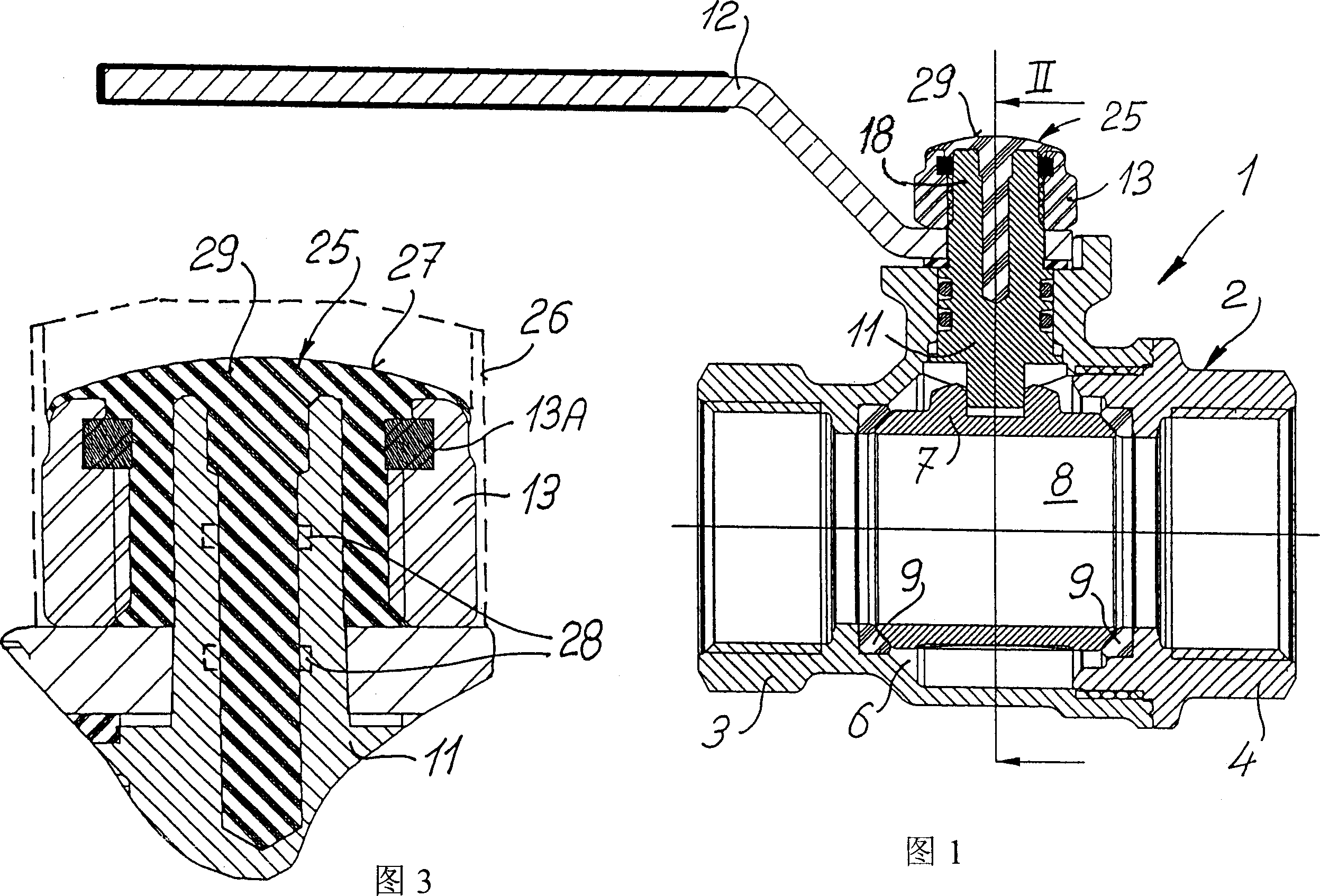
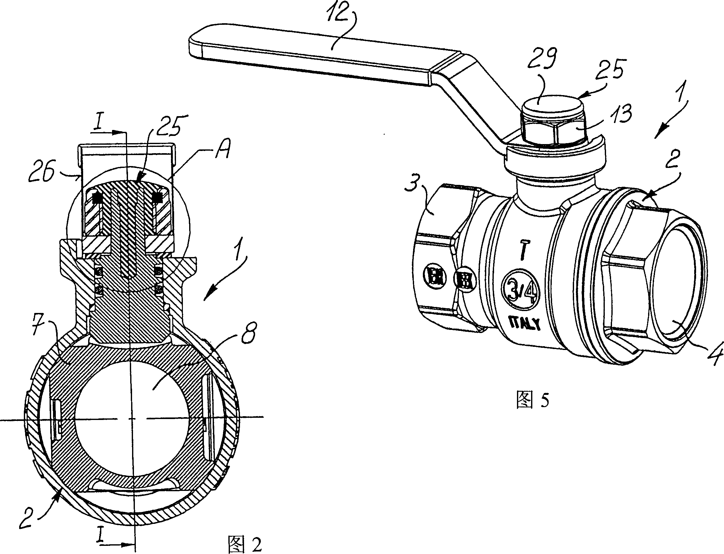
[0037] With reference to prior ball valve 1, such as coal ball valve, it comprises valve body 2, and inlet 3 is arranged on it, outlet 4, vice versa also can, the middle of the two is inner cavity 6. A spherical valve 7 can be adorned in the inner cavity, supported by two washers 9 opposite and engaged with the drive screw 11, a through hole 8 is arranged in the valve 7. Can assemble a transmission rod 12 that geometric shape cooperates with it on the screw rod 11, and clamp on the screw rod 11 with fastening nut 13.

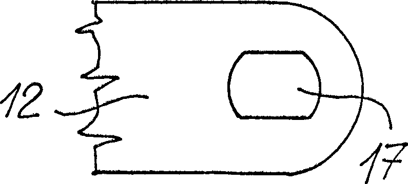
[0038] As shown in Figure 4, in order to make the geometry of the transmission rod 12 and the screw rod 11 fit well, in the shown embodiment, there are two opposite planes 14, 16 on the screw rod 11, and there are corresponding recesses on the transmission rod 12. mouth 17, see Figure 4A .

[0039] In the threaded end 18 of the screw 11 there is an axial blind hole 19 . When ...


PUM


Abstract

An improved ball valve (1), in particular for gas systems, comprises a tampering indicating seal (25) made by injection molding a synthetic or metal material into cavities (19; 21; 22) formed in the screw-clamping nut assembly (11, 13) and including a cap outer portion (29) which substantially covers the surface of the outer face of the nut (13) and/or extending (29A) on the side surface of said nut (13).

Description

technical field [0001] The present invention relates to an improved gas system valve, an improved design ball valve specially used for domestic and industrial gas systems. Background technique [0002] Ball valves for general use and those specially used for domestic and industrial gas systems can choose a damage display device to clearly show possible damage to manual parts of the valve such as operating handles, operating rods, etc., hereinafter collectively referred to as "transmission rods". The drive rod is combined with a geometrically matched screw rod and clamped to the screw rod by a clamping nut engaging the threaded free end of the screw rod in order to rotate the ball lock of the valve. [0003] The above-mentioned geometric fit is usually realized by two parallel and opposite planes on the free end of the thread and the corresponding holes on the transmission rod. The two sections of sidelines of the hole connected to the two planes are part of a circle, and th...

Claims


Application Information

Patent Timeline
IPC IPC(8): F16K5/06F16K35/00F16B41/00
CPCF16K5/0647F16B41/005F16K35/00Y10T137/7062Y10T137/8811
Inventor 卢卡·贾科米尼
Owner 贾科米尼公开有限公司
Why Eureka
Try Eureka