Container for fuel cell,fuel cell and electronic apparatus

A fuel cell and container technology, applied in the direction of fuel cells, fuel cell groups, fuel cell components, etc., can solve problems such as hindering electrochemical reactions and degrading power generation efficiency, achieve high reliability and safety, and improve mechanical reliability excellent corrosion resistance

Inactive Publication Date: 2007-01-31
KYOCERA CORP
View PDF5 Cites 0 Cited by
  • Summary
  • Abstract
  • Description
  • Claims
  • Application Information

AI Technical Summary

Problems solved by technology

However, in the conventional fuel cell 21, to extract electricity from the fuel electrode and the air electrode sandwiching the electrolyte member 23, there is only a method of drawing connection to the outside, or using the gas separator 26 as a conductive material, overlapping and connecting in series. approach, for small fuel cells there is a problem with making this difficult
[0024] In addition, if dust or the like enters the gas flow path 28 or the air flow path 29, or blocks the gas flow path 28 or the air flow path 29, or adheres to the surface of the gas flow path 28 or the air electrode 25, it is difficult to pass through the gas flow path. 28 or the air flow path 29, supplying fuel gas or air as an oxidizing gas to the fuel electrode 24 or the air electrode 25 hinders the electrochemical reaction in the electrolyte member 23, so there is also a problem of deterioration in power generation efficiency.

Method used


Image

  • Container for fuel cell,fuel cell and electronic apparatus
  • Container for fuel cell,fuel cell and electronic apparatus
  • Container for fuel cell,fuel cell and electronic apparatus

Examples


Embodiment Construction

[0054] Hereinafter, preferred embodiments of the present invention will be described in detail with reference to the drawings.

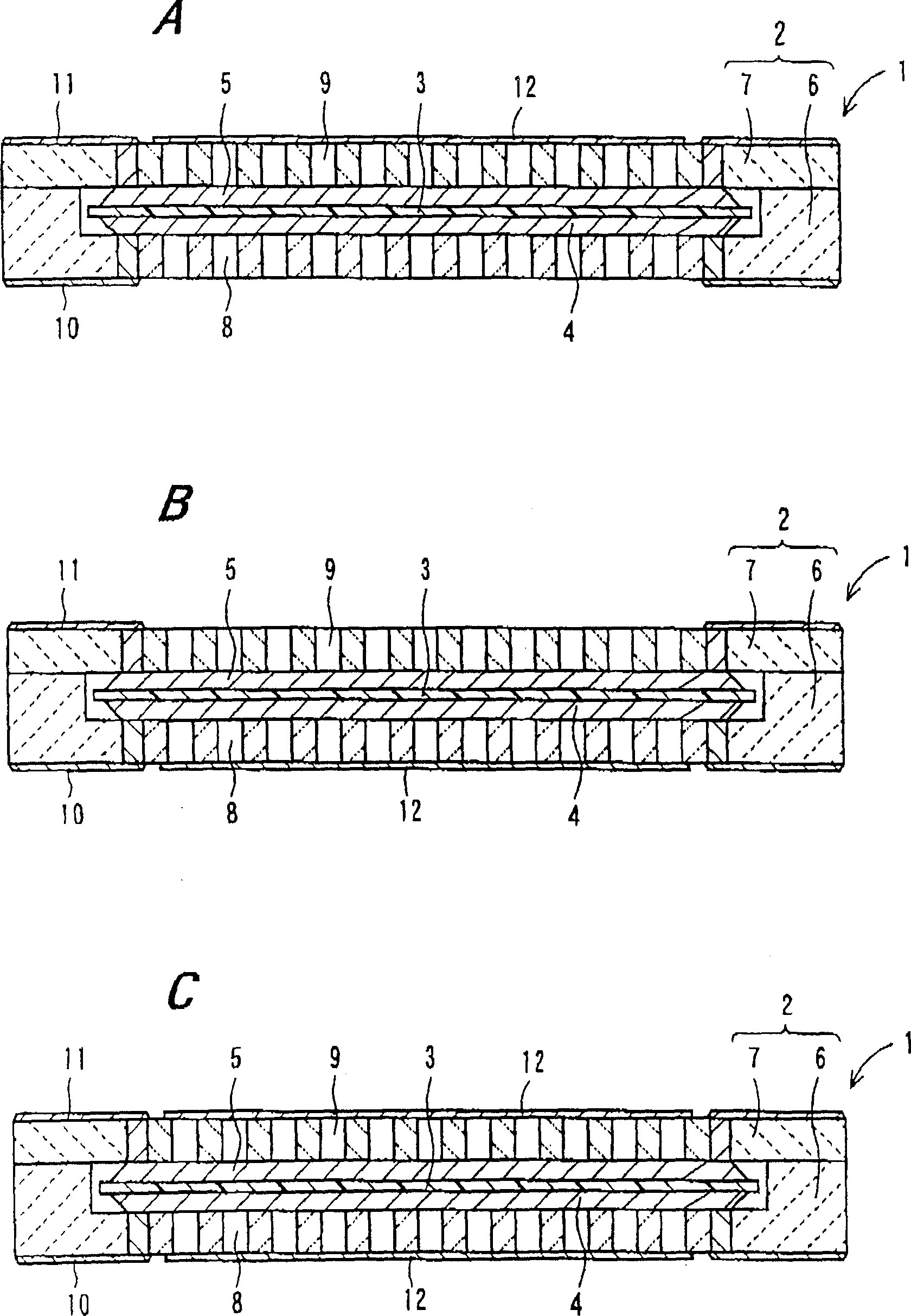
[0055] figure 1 A~ figure 1 C is a cross-sectional view showing a fuel cell container and a fuel cell using the same according to an embodiment of the present invention. exist figure 1 A~ figure 1 In C, 1 is a fuel cell, 2 is a container for a fuel cell, 3 is an electrolyte member, 4 is a first electrode, 5 is a second electrode, 6 is a substrate, 7 is a cover, 8 is a first fluid flow path, 9 Reference numeral 10 denotes a second fluid flow path, 10 denotes a first wiring conductor, 11 denotes a second wiring conductor, and 12 denotes a porous body.

[0056] In the electrolyte member 3 of the present invention, for example, a fuel electrode (not shown) serving as an anode-side electrode and an air electrode (not shown) serving as a cathode-side electrode are integrally formed on both main surfaces of an ion-conducting membrane (exchange membr...


PUM

PropertyMeasurementUnit
bending strengthaaaaaaaaaa
thicknessaaaaaaaaaa
porosityaaaaaaaaaa

Abstract

PURPOSE: Provided are a container for a fuel cell which can accommodate an electrolyte member, is compact and strong, and can allow gas to be distributed uniformly and temperature to be gradient uniformly, a fuel cell containing the container for portable electronic device, and an electronic tool containing the fuel cell. CONSTITUTION: The container comprises a base body which comprises a ceramic a concave part accommodating an electrolyte member having first and second electrodes at one and the other main faces, at the one side; a first fluid channel which is formed from the bottom face of the concave part facing the one main face of the electrolyte member to the outer face of the base body; a first wire conductor whose one end is located at the bottom face of the concave part facing the first electrode of the electrolyte member and whose the other end is drawn to the outside of the base body; a cover body which is installed by covering the one side of the environment of the concave part of the base body with the concave part and seals tightly the concave part; a second fluid channel which is formed from the one side of the cover body facing the other main face of the electrolyte member to the outer face of the cover body; a second wire conductor whose one end is located at the one face of the cover body facing the second electrode of the electrolyte member and whose the other end is drawn to the outside of the cover body; and a porous body which is located at the base body or the cover body so as to cover one of the first and second fluid channels where an oxidizing gas is supplied.

Description

technical field [0001] The present invention relates to a small and highly reliable fuel cell container made of ceramics for accommodating an electrolyte member, a fuel cell and an electronic device using the same. Background technique [0002] In recent years, the development of small fuel cells that operate at lower temperatures than before has been actively developed. Among the fuel cells, solid polymer electrolyte fuel cells (Polymer Electrolyte Fuel Cell: hereinafter referred to as PEFC) and phosphoric acid fuel cells, or solid electrolyte fuel cells are known depending on the type of electrolyte used. [0003] Among them, PEFC, the working temperature is low temperature in the range of 80 ~ 100 ℃, has the following excellent characteristics: [0004] (1) High output density, miniaturization and light weight; [0005] (2) Since the electrolyte is non-corrosive and the working temperature is low, in terms of corrosion resistance, it is less restricted by the materials ...

Claims


Application Information

Patent Timeline
Patent Type & Authority Patents(China)
IPC IPC(8): H01M8/02H01M8/00H01M2/02
CPCY02E60/50H01M8/02H01M8/24
Inventor 菅井广一朗
Owner KYOCERA CORP
Why Eureka
Try Eureka