Floating circular current oil receiver and circular current separating method

A technology of oil collector and ring pipe, which is applied in the field of on-site treatment and collection of oily sewage in petroleum exploration, storage and transportation, processing and other petrochemical processes. Efficiency, free adjustment of kinetic energy, ensuring the effect of adjustment function

Active Publication Date: 2007-02-14
抚顺市明尧石油机械有限公司
View PDF2 Cites 0 Cited by
  • Summary
  • Abstract
  • Description
  • Claims
  • Application Information

AI Technical Summary

Problems solved by technology

[0008] 2. Multi-layer outlets can also be used to reduce the high water level, but due to the floating liquid level, the position of the oil-water interface cannot be determined, and the operation is difficult;
[0009] 3. There are also facilities that use floating funnels to collect oil, but due to the huge water surface, the floating oil has no moving power, so the effect is limited
However, due to its harsh operating conditions, high energy consumption and operating costs, it is difficult to promote, so it cannot replace the status of the traditional "old three sets" so far

Method used


Image

  • Floating circular current oil receiver and circular current separating method
  • Floating circular current oil receiver and circular current separating method

Examples


Embodiment 1

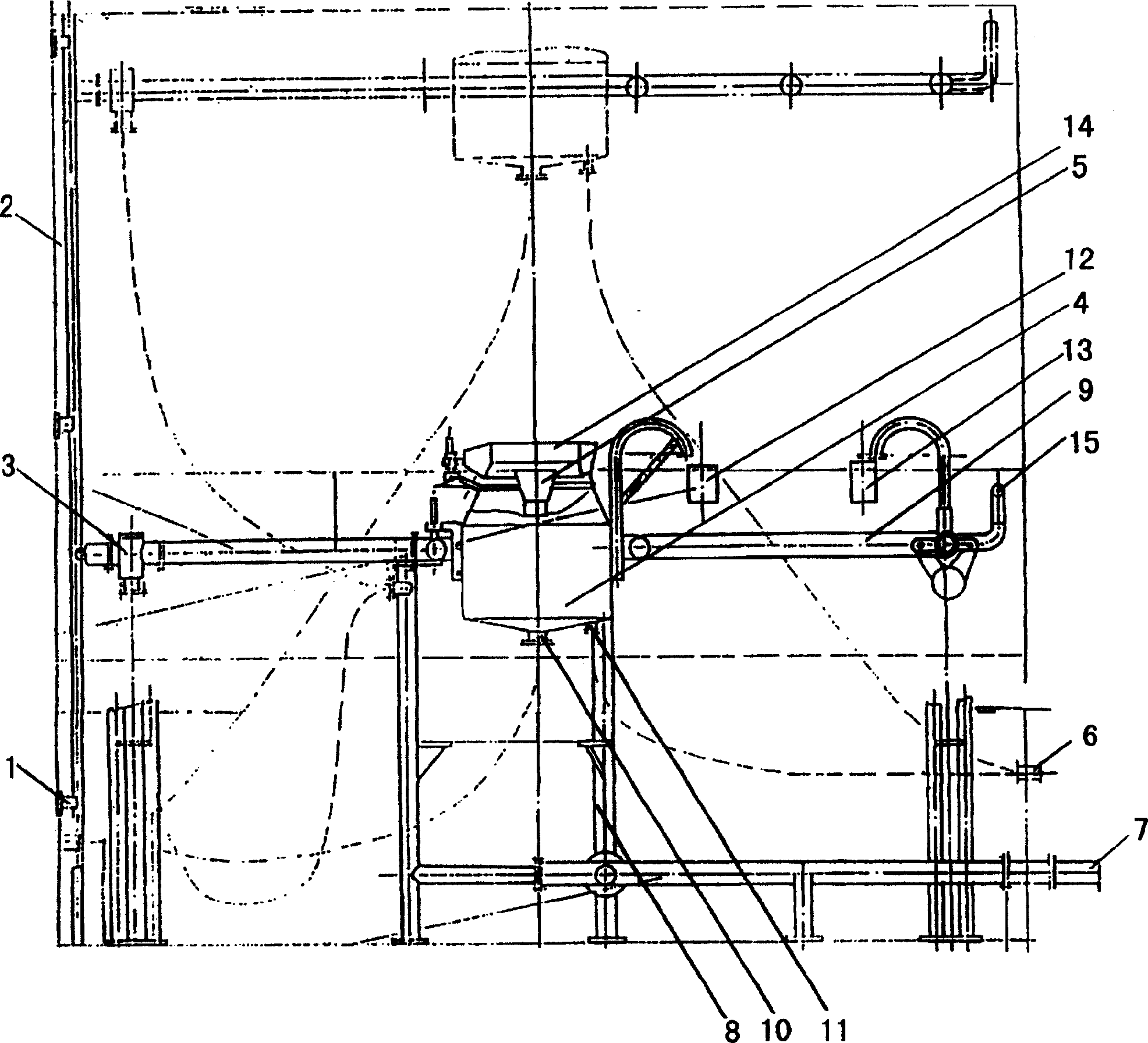
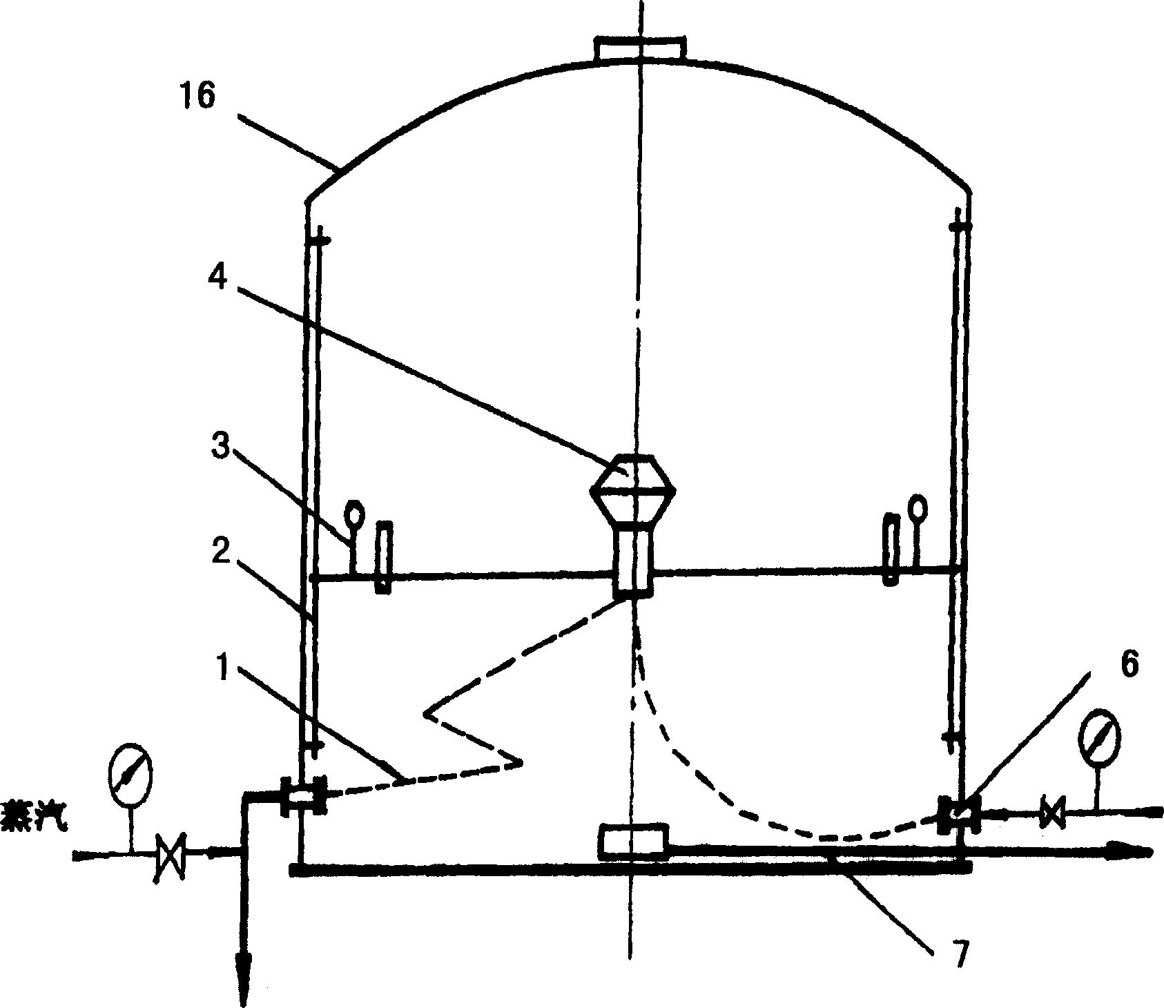
[0050] like figure 1 As shown, the oil collection tank 4 of the present invention, the ring pipe 9 and the water inlet pipe system 6 are all arranged in the container 16, the oil collection tank 4 is connected to the ring pipe 9 by a chain, and the bottom of the oil collection tank 4 and the ring pipe 9 is provided with a support rod 8; The oil collecting ring 14 on the upper part of the oil collecting tank 4 is provided with an oil collecting bucket 5; the oil collecting bucket 5 is connected to the oil outlet pipe 1; The lower part of the tank is provided with an outlet pipe 7 for ensuring the minimum storage, homogenization, precipitation and separation time requirements of the liquid in the container 16; the outer surface of the oil collection tank 4 is provided with an oil collection tank buoy 12; ring pipe buoys are evenly distributed on the ring pipe 9 13 and the water jet pipe 15, the buoy 3 is located at the junction of the ring pipe 9 and the water inlet pipe system ...

Embodiment 2

[0082] The present invention can also be arranged in the oily sewage pond, other is the same as embodiment 1.

Embodiment 3

[0084] The present invention can also be arranged in the wide water area that is rich in oily sewage, other is the same as embodiment 1.


PUM


Abstract

The floating circular current oil receiver and circular current separating method are suitable for in-situ processing of oil-contaminated water in petroleum exploration, acquisition, accumulating, process and other landification processes; fore treatment in oil-contaminated water treatment plants, substituted oil removal, air-float, as well as other separation and elimination of mixing liquids with different proportions. The oil collection tank is connected with an endless tube, with its lower part equipped with a support lever; the oil collection bucket inside the oil collection ring at the upper side of the oil collection tank is connected with a flowline; the oil collection tank water outlet at lower part of the oil collection tank is connected with a water pumping equipment set outside; an water outlet pipe is set at lower part of the container; an oil collection tank float bowl is mounted at the outer side of the oil collection tank; a float bowl, an endless tube float bowl and a water-jet tube are set above the endless tube; the water inlet pipe system is connected with the endless tube ; the endless tube cooperates with a pulley at the conductor bar. Said circular current separating method is as follows: the greasy dirt water enters into the water inlet pipe system from the water intake, the floating oil at the solution surface is caused to flow to the oil collection tank and the oil collection bucket and is discharged from the flowline; after separation, purified water is discharged from the water outlet pipe; the water outlet is connected with the water pumping equipment set outside to constitute a recycle loop for reciprocating movement. The invention possesses the advantages of energy conservation and reduced volume.

Description

technical field [0001] The invention relates to a floating circulation oil collector and a circulation separation method, which is especially suitable for in-situ treatment of oily sewage in oil exploration, collection, storage and transportation, processing and other petrochemical processes; the pretreatment of oily sewage treatment plants replaces oil separation, Separation and removal of air flotation and other mixed liquids with different specific gravity. Background technique [0002] At present, the sewage degreasing technology in the domestic existing technology is mainly based on the treatment process of gravity separation, which generally consists of the "old three sets" of processes such as adjustment, oil separation, and air flotation. [0003] In the process of oil exploration, collection, storage and transportation, refining and other petrochemical processing, there are containers for different purposes, including tanks and pools, in the process of oily sewage c...

Claims


Application Information

Patent Timeline
Patent Type & Authority Patents(China)
IPC IPC(8): B01D17/032
Inventor 庞景宾
Owner 抚顺市明尧石油机械有限公司
Why Eureka
Try Eureka