Supercharge Your Innovation With Domain-Expert AI Agents!

Improvement of thermal conductivity and luminosity promote structure of LED

A technology of light-emitting diodes and heat conduction, applied in semiconductor devices, electrical components, circuits, etc., can solve the problems of hindering the conduction and heat dissipation of light-emitting diodes, affecting the light-emitting effect or lighting effect, and failing to exert their due, so as to increase the length of the beam irradiation. , Improve the heat dissipation effect, the effect of good heat dissipation effect

Inactive Publication Date: 2007-02-28
陈聪欣
View PDF2 Cites 0 Cited by
  • Summary
  • Abstract
  • Description
  • Claims
  • Application Information

AI Technical Summary

Problems solved by technology

[0008] However, from the above-mentioned various previous citations, it can be found that the upper ends of all known traditional light-emitting diode brackets are encapsulated with transparent bodies, and the entire area of ​​the bottom of the cathode bowl is covered with a film with a thickness of about 20um-100um. Adhesive (also divided into silver glue, white glue, and insulating glue) is used to attach the chip of the light-emitting diode, but it is also the main reason for hindering the conduction and heat dissipation of the residual heat of the light-emitting diode due to these two, because no matter the light-emitting diode with large or small power Chips generate different proportional heat sources at various levels due to different powers during the turn-on and lighting. Whether the heat source can be quickly conducted and dissipated will strictly affect the luminous effect or lighting effect produced by the light-emitting diode? However, the adhesive coated on the bottom and the resins (A, B glue) on the upper and side packaging tightly and meticulously encapsulate the wafer into a huge sealing body (its ratio is higher than that of the molecules and atoms of the wafer material), resulting in The brightness, quality, efficiency, and lifespan of light-emitting diodes cannot play their due high-efficiency functions; therefore, how to make some improvements to change its space or function form to solve the above problems has not been discussed in the above-mentioned patent cases. hint or expose

Method used


Image

  • Improvement of thermal conductivity and luminosity promote structure of LED
  • Improvement of thermal conductivity and luminosity promote structure of LED
  • Improvement of thermal conductivity and luminosity promote structure of LED

Examples


Embodiment Construction

[0068] Referring to the accompanying drawings, specific embodiments of the present invention will be described in detail.

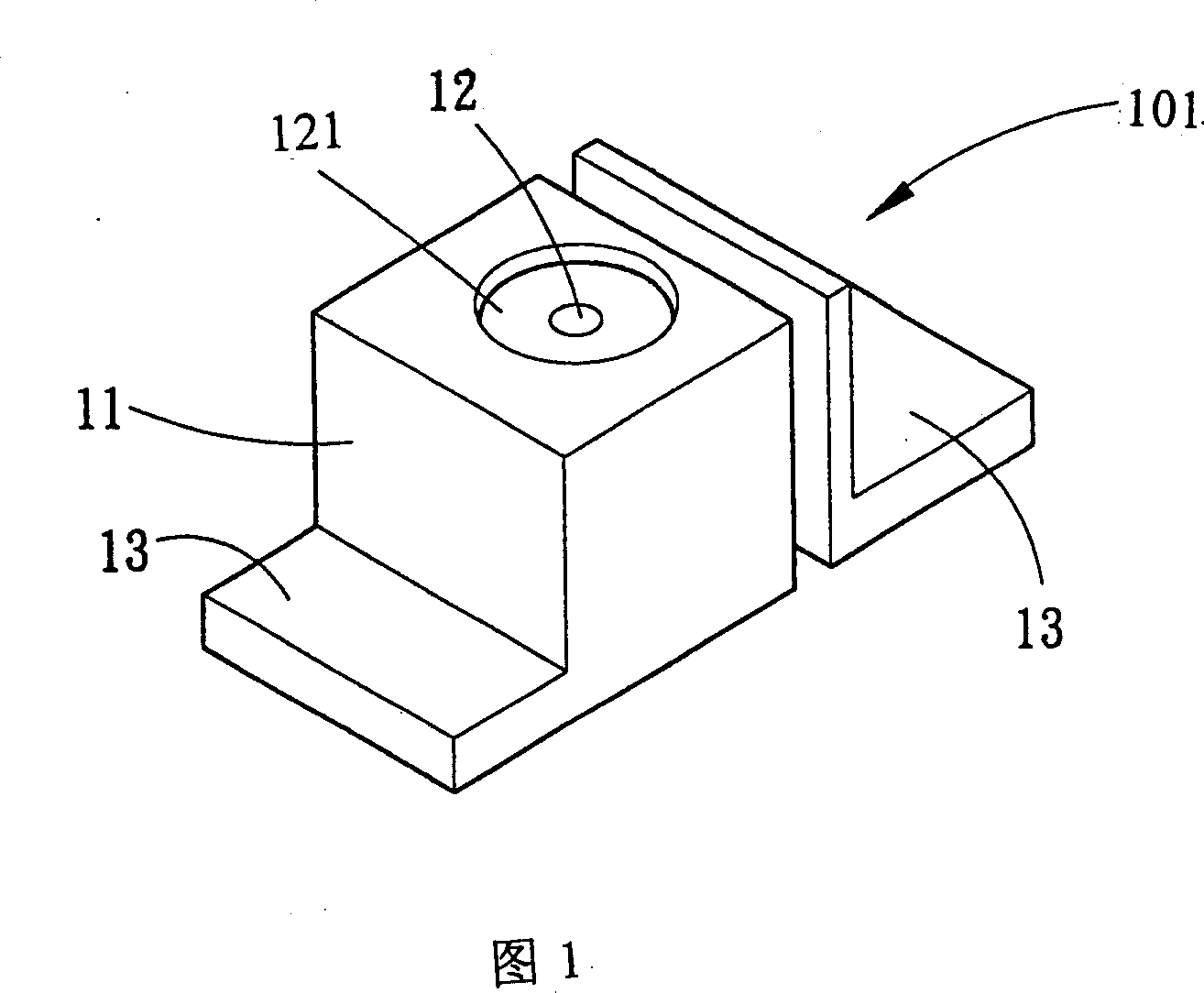
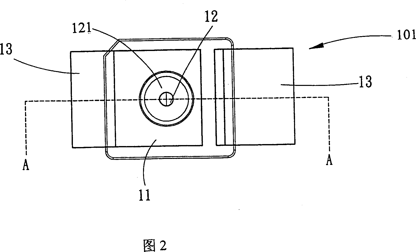
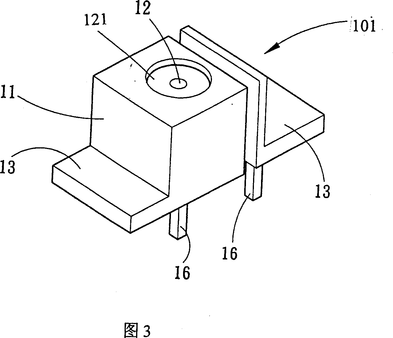
[0069] Referring to Fig. 1 to Fig. 21, it can be clearly seen that the heat conduction and luminosity structure of the light-emitting diode provided by the present invention is mainly aimed at brackets 101 (double cooling fins), 102 (four cooling fins), 103 ( No cooling fins) (or other feasible shapes) on the cathode stand 11 upper end forms a bowl cup structure 121,122,123,124, for holding light-emitting chip 150 in above-mentioned bowl cup 121,122,123,124 most The bottom is at least provided with a concave portion 12 whose diameter or area is relatively smaller than the bottom surface of the light-emitting chip (the best is between 15% and 35% of the area of ​​the bottom surface of the chip, and the feasible implementation range is between about 5% and 95%), and the concave portion The shape of 12 can be round, square, rectangular, rhombus, etc., and th...


PUM


Abstract

A structure promotes heat conduction and brightness for luminescent diode. It forms a bowl structure at cathode foot reset on the support to hold the light emitting wafer; the main feature is that at least one cove of which diameter and area is no less than light emitting wafer is located on the bottom of this bowl for filling the adhesive to adhere one or several wafers, makes the bottom of bowl and other part connecting with wafer are not obstructed by adhesive, therefore there is a good heat conduction and heat emission effects; furthermore, at least one bore can be formed on the cove positioned between the hollow out place of the above cathode support and the bowl to benefit giving out adhesive in the manufacturing process, furthermore can make the bore forming the heat convection channel with outside air to further disperse the heat produced as the wafer lightening. The above structure can largely promote the heat emission performance for luminescent diode, further promote the brightness, reliability and life of luminescent diode, also can save energy.

Description

technical field [0001] The invention relates to a heat conduction and luminosity raising structure of a light emitting diode, in particular to a bowl cup structure designed on the cathode stand of the light emitting diode bracket. Background technique [0002] At present, the relevant light-emitting diode bracket mainly includes: a cathode pin is formed by a metal sheet, a groove is included at the upper end for fixing the chip, and an anode pin is formed by another metal sheet, which is the prior art. For example, Taiwan Patent Announcement No. 506626 "Structure Improvement of Light-Emitting Diode", Announcement No. 488616 "Light-Emitting Diode Support", Announcement No. 486153 "Light-Emitting Diode Support" and Announcement No. 441860 "Light-Emitting Diode Support" New patents such as "Stent Improvement Structure of the Body" all suggest the above-mentioned typical traditional structure in succession. [0003] In the above-mentioned patent case, it is revealed that the st...

Claims


Application Information

Patent Timeline
IPC IPC(8): H01L33/00
Inventor 徐杏芬
Owner 陈聪欣
Features
  • R&D
  • Intellectual Property
  • Life Sciences
  • Materials
  • Tech Scout
  • Unparalleled Data Quality
  • Higher Quality Content
  • 60% Fewer Hallucinations
Learn More