
Screw anchored joint prosthesis

A hip joint prosthesis, screw technology, applied in the direction of the prosthesis, shoulder joint, ankle joint, etc., can solve problems such as overall instability

Inactive Publication Date: 2007-04-04
斯罗博丹·特皮克 +1
View PDF3 Cites 1 Cited by
  • Summary
  • Abstract
  • Description
  • Claims
  • Application Information

AI Technical Summary

Problems solved by technology

[0011] *In the acetabular component, the difficulty of matching the implant to the highly compliant spongy bone, with or without cement, can lead to the formation of soft tissue at the interface so that general instability can develop;

Method used


Image

  • Screw anchored joint prosthesis
  • Screw anchored joint prosthesis
  • Screw anchored joint prosthesis

Examples


Embodiment Construction

[0040] current technology

[0041] As discussed in detail above, cemented and uncemented (mortarless) hip prostheses have now become an expanding industry with its identified problems, including loss of bone due to movement of the diaphysis and bone at the interface; soft tissue formed at the interface can develop gross instability; and osteolysis can develop global loosening or even fracture of the prosthetic components. While the design disclosed in the '654 patent addresses many of these problems, there is still much room for improvement from a surgical standpoint.

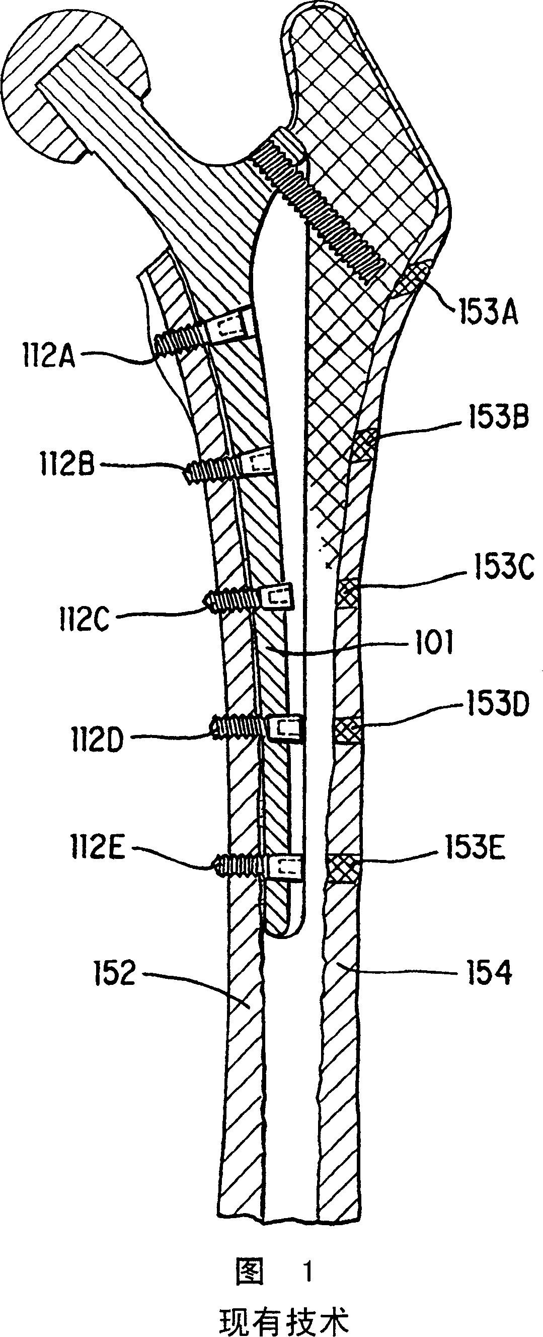
[0042] Cementless, screwed femoral components are known in the art, such a component as disclosed in the '654 patent is shown in FIG. 1 . Screws 112A through 112E attach the femoral components to the mesocortex 152, thus overcoming some of the problems with cemented femoral components. However, this design requires trauma to a part of the patient's body that is not required for long-term immobilization of the...


PUM

PropertyMeasurementUnit
angleaaaaaaaaaa

Abstract

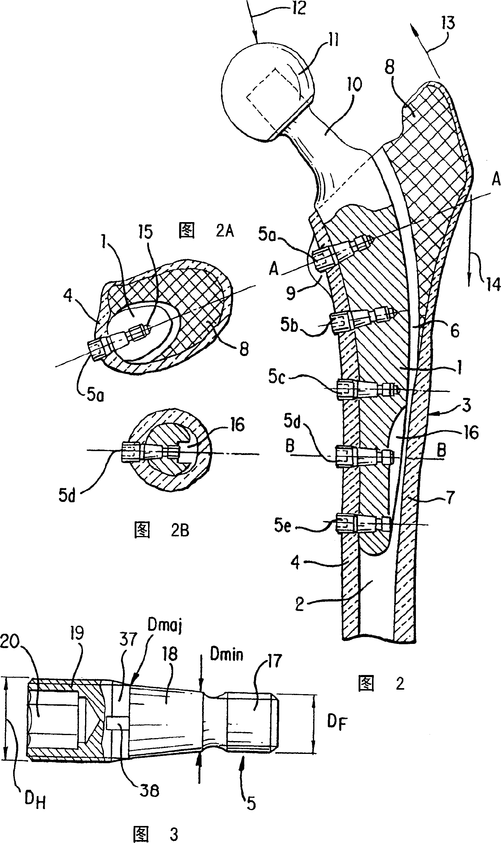
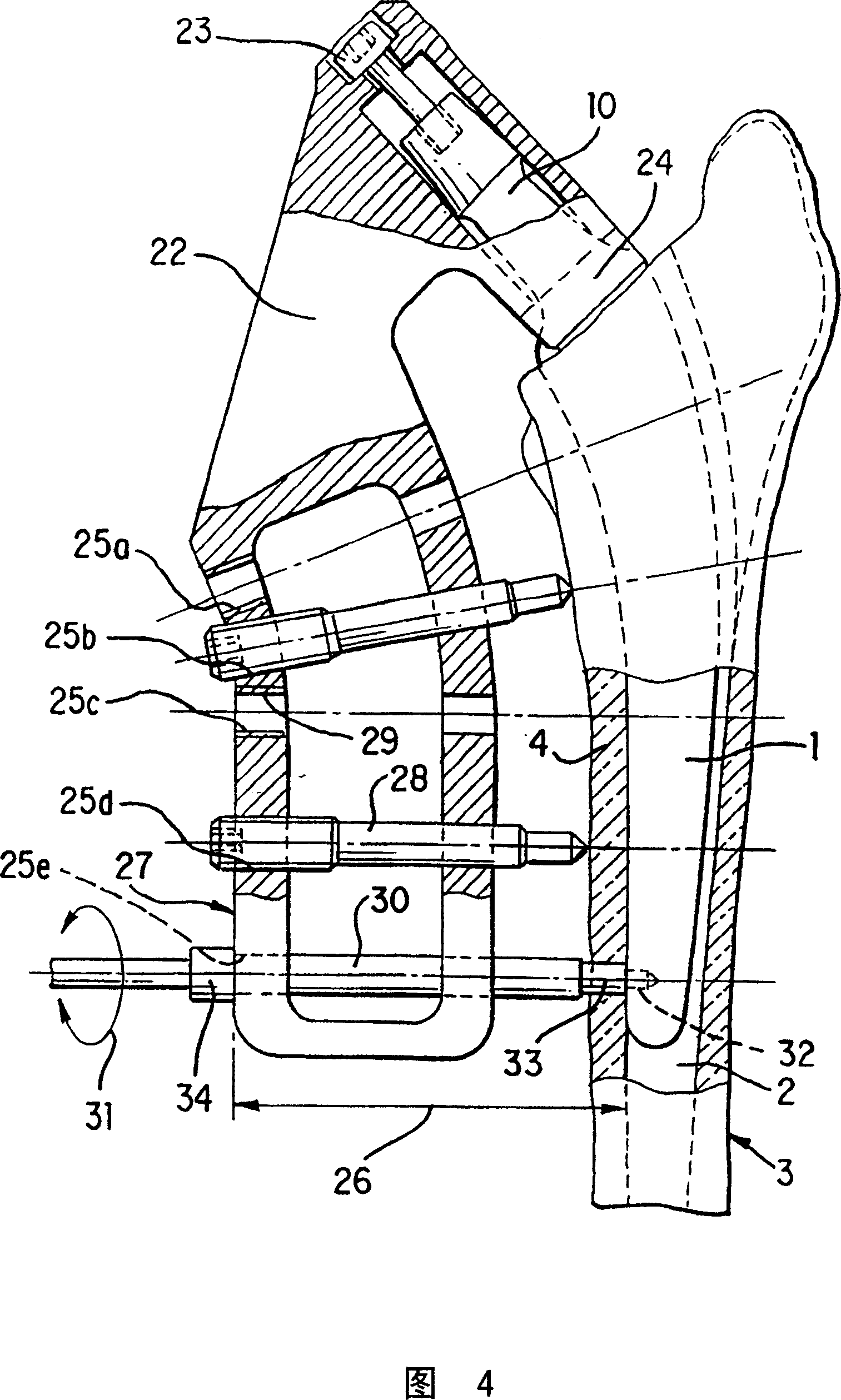
Screw-based primary fixation of the prosthetic components within the medullary cavity solves the problem of micro-movements encountered in conventional press-fit cementless fixation. For a total hip prosthesis, the stem is fixed to the medial cortex of the proximal femur by the medial approach alone, obviating the need for drilling of the lateral cortex. The stem may be implanted using special drill guide instrumentation. Anchoring screws are locked into the stem of the femoral component, while self-cutting threads on the screw head engage the pre-drilled medial cortex. This novel fixation principle can also be applied to other joint prostheses, e.g. finger, shoulder, elbow and knee, as well as to dental and spinal implants.

Description

technical field [0001] The present invention generally relates to an improved joint prosthesis. Background technique [0002] In the three decades since total hip replacement (THR) became widely accepted, the practice of orthopedic surgery has changed. A whole new industry has sprung up in support of THR. More importantly, THR has improved the quality of life of millions of patients in a procedure unmatched by any other single procedure in the history of surgery. All of this was originally possible with the advent of cemented THR. Within the first decade following Charnley's pioneering work, a broad base of surgeon training, a highly stimulated industry, and an enabling health insurance policy had led to worldwide acceptance of THR, as evidenced by the number of people undergoing this procedure. Exponential growth, currently proven in over 600,000 per year worldwide. [0003] But this early period of boundless optimism was followed by waves of innovation, when results of ...

Claims


Application Information

Patent Timeline
Patent Type & Authority Patents(China)
IPC IPC(8): A61F2/32A61B17/58A61B17/17A61B17/72A61B17/86A61B17/88A61F2/00A61F2/30A61F2/36A61F2/40A61F2/42A61F2/44
CPCA61B17/725A61F2002/30878A61F2002/30485A61F2002/30112A61F2/3662A61B17/7291A61F2002/3082A61F2002/30405A61B17/86A61F2230/0004A61F2002/30685A61F2/4241A61F2/367A61F2/40A61F2002/3611A61F2002/30797A61F2310/00011A61F2310/00407A61B17/1753A61F2002/30813A61F2002/30795A61F2/3676A61F2002/3643A61F2/30767A61F2002/30774A61F2310/00796A61F2230/0013A61B17/8875A61F2220/0025A61F2002/365A61F2002/3079A61F2002/30787A61B17/1735A61F2002/3081A61F2/30723A61F2002/30662A61F2002/30158A61F2310/00179A61F2002/30131A61F2/36A61F2/44A61F2002/3625A61F2002/30332A61F2220/0033A61F2002/368A61B17/72A61F2230/0026A61F2002/30785A61F2002/4251A61F2002/3631A61F2002/30772
Inventor 斯罗博丹·特皮克安德鲁·W·霍奇
Owner 斯罗博丹·特皮克
Learn More