Cast secondary part for electric motors

A motor and secondary technology, which is applied to the device implementing the method to manufacture the secondary part, can solve the problems of improving the dimensional accuracy of the casting body, long processing cycle, etc., and achieve the effect of good dimensional accuracy and short cycle manufacturing time

Inactive Publication Date: 2007-04-04
SIEMENS AG
View PDF8 Cites 0 Cited by
  • Summary
  • Abstract
  • Description
  • Claims
  • Application Information

AI Technical Summary

Problems solved by technology

[0005] Although satisfactory product results can be achieved by this known method, the requirements for the dimensional accuracy of the cast body are increased
Furthermore, due to the unavoidable hardening and reaction times of the casting materials, this results either in relatively long processing cycles or in the necessity of simultaneously using several molds in production

Method used


Image

  • Cast secondary part for electric motors
  • Cast secondary part for electric motors
  • Cast secondary part for electric motors

Examples


Embodiment Construction

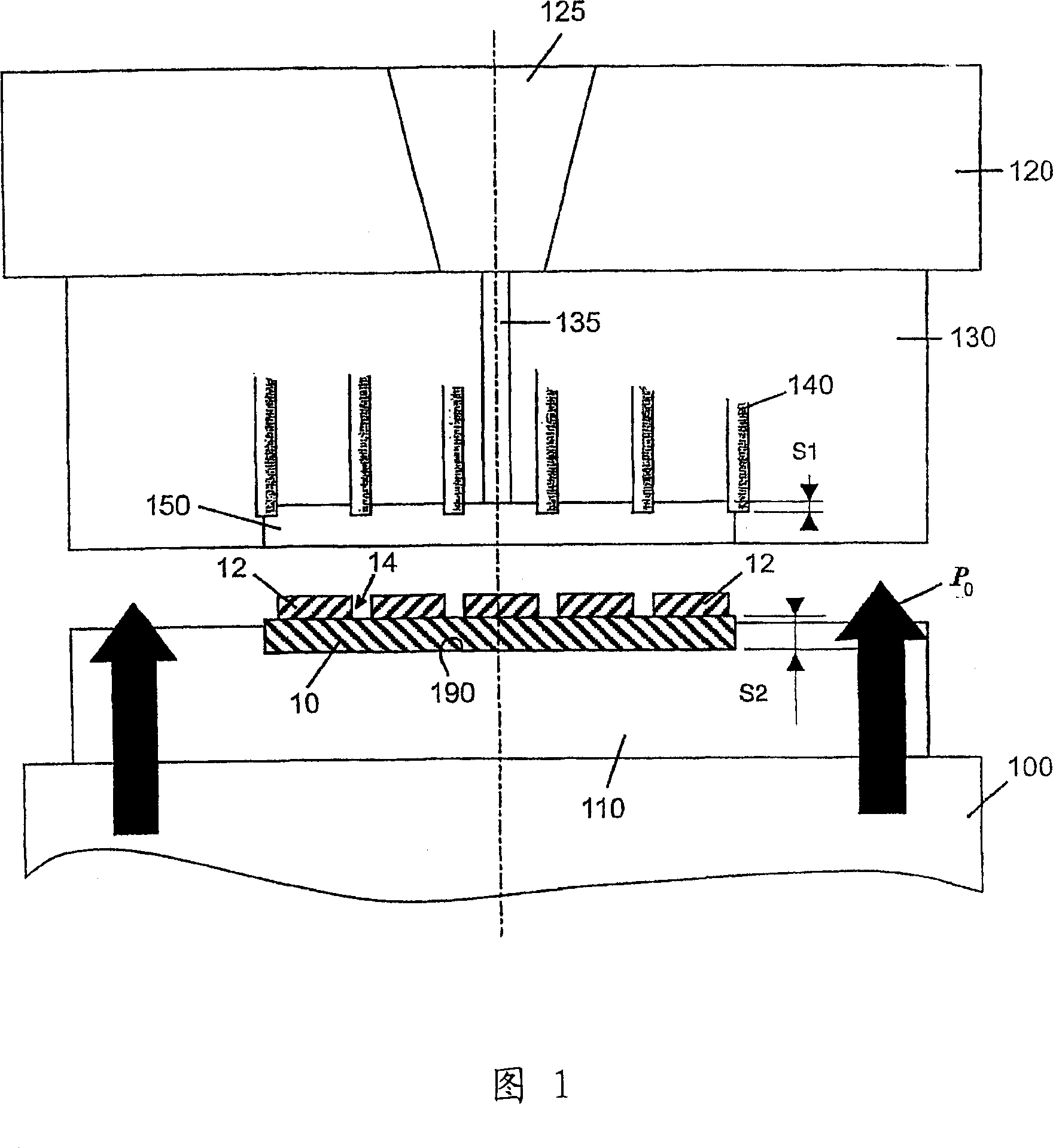
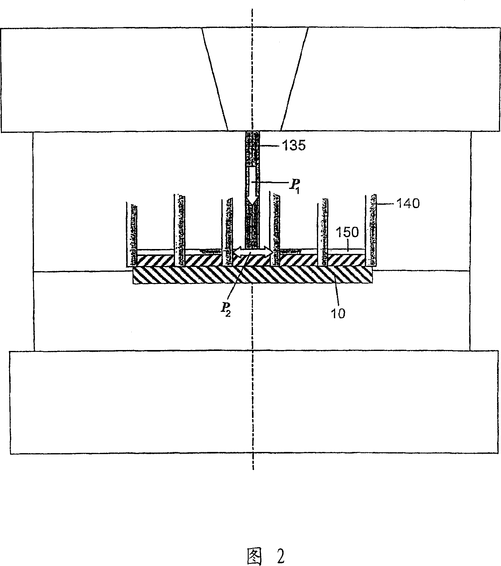
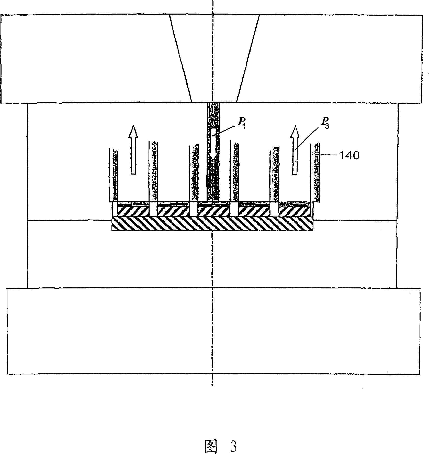
[0024] According to FIG. 1 , a movable mold platen 100 carries a first mold half 110 , while a second mold half 130 is assembled on a fixed mold platen 120 . A nozzle channel 125 , which opens into a casting channel 135 in the second mold half 130 , is formed in the fixed fastening plate 120 . The casting channel 135 itself opens into a cavity 150 in the second mold half 130 . In addition, the second half-form 130 has positioning pins 140 that can be moved into or out of the cavity 150 .

[0025] The first half 110 includes a recess 190 for receiving a support element 10 . This carrier element 10 is a known per se carrier plate of magnetizable material on which, in a known per se manner, gaps 14 are provided and cuboidal magnetic elements 12 are arranged in a straight line. The permanent magnets are preferably prefixed by gluing or the like.

[0026] After the carrier plate 10 with the permanent magnets 12 arranged thereon has been inserted into the groove 190, for example ...


PUM


Abstract

The invention relates to a secondary part for a motor, comprising at least one support element (10) and several permanent magnets (12) and a cast body made of plastic, whereby the permanent magnets (12) are cast therein. According to the invention, the cast body is made of a synthetic cast material. According to the inventive method, the cast body is produced in a form tool (110, 130) of an injection moulding machine. Positioning elements (140) are provided in the form tool (130) in order to fix the permanent magnets (12) on the support element (10). Said positioning elements are withdrawn from the cavity of the form tool after the first filling phase. The empty spaces arising therefrom are filled in a second filling phase.

Description

technical field [0001] The invention relates to a cast secondary part for an electric motor, a method for producing the secondary part and a device for carrying out the method. Background technique [0002] The secondary part is used in a synchronous motor designed as a rotary motor or as a linear motor, which usually has a carrier element made of magnetizable material and a plurality of primary parts connected to an electrical feed-in during operation permanent magnets acting together. To prevent damage and corrosion, the permanent magnets are embedded in a cast body, for example made of polyurethane or epoxy resin (see DE-A-199 36 064). [0003] In the known method, a support element equipped with permanent magnets is inserted into a mould, and polyurethane or epoxy resin is poured into the mould, increasing the pressure and temperature if necessary, so as to ensure that the casting material is completely squeezed into the in all cavities. Furthermore, in order to ensur...

Claims


Application Information

Patent Timeline
IPC IPC(8): H02K15/03H02K41/03B29C45/26B29C45/14B29C45/16H02K1/27H02K15/12
CPCH02K1/27H02K15/03
Inventor 托马斯·霍普赫尔曼·赛勒
Owner SIEMENS AG
Why Eureka
Try Eureka