
Rotary actuator device for controlling the stroke of a gas-shuttle poppet valve in the cylinder head of an internal combustion engine

A technology for cylinder and stroke control of an internal combustion engine, applied to valve drive devices, non-mechanically actuated valves, valve devices, etc., can solve the problems of unstable control cam position and continuous load on the power grid on the vehicle, avoiding overshoot, structural small space effect

Inactive Publication Date: 2007-07-11
BAYERISCHE MOTOREN WERKE AG
View PDF6 Cites 0 Cited by
  • Summary
  • Abstract
  • Description
  • Claims
  • Application Information

AI Technical Summary

Problems solved by technology

Although this known oscillation of the spring energy in the known valve train also serves to reduce the consumption of electrical energy of the rotary actuator, a disadvantage exists in the known rotary actuator in particular in that, in the case of mushrooms When the valve is closed, the position of the control cam is unstable due to the tappet in the top area under the action of the pre-tightened valve opening spring. When a small amount deviates from the top of the cam on the control cam, the tappet produces a rotation direction or reverse rotation direction. torque, which has to be compensated by the respective counter-torque of the controlled electric rotary actuators, especially when the internal combustion engine is stopped, which causes a constant load on the on-board electrical network

Method used


Image

  • Rotary actuator device for controlling the stroke of a gas-shuttle poppet valve in the cylinder head of an internal combustion engine
  • Rotary actuator device for controlling the stroke of a gas-shuttle poppet valve in the cylinder head of an internal combustion engine

Examples


Embodiment Construction

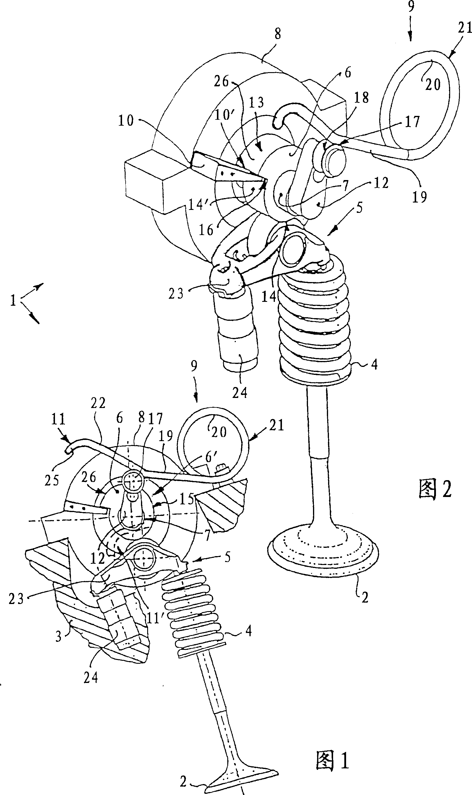
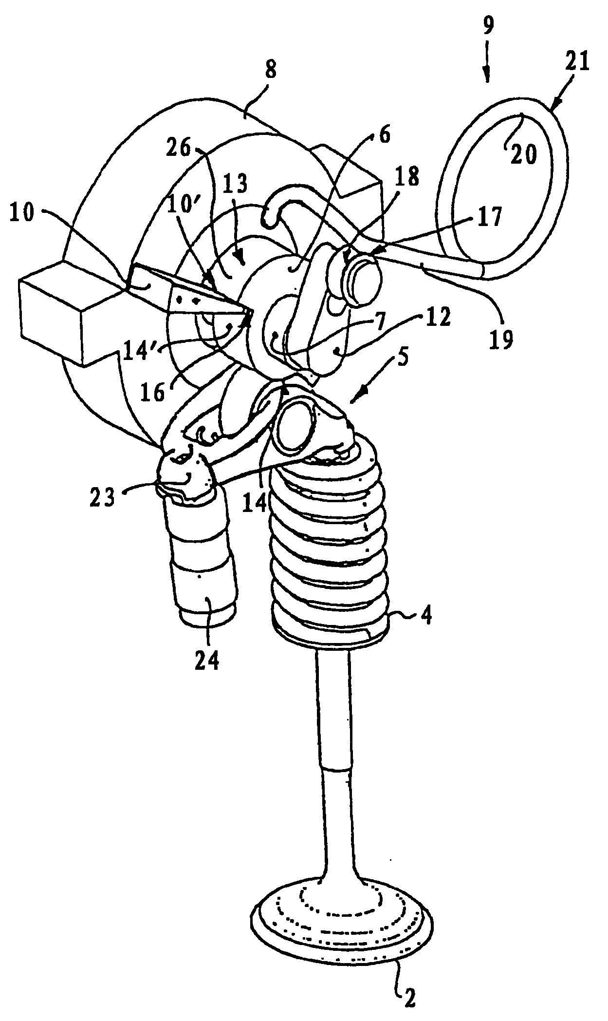
[0026] In a rotary actuator 1 for stroke control of a mushroom valve 2 in a cylinder head 3 not shown in detail of an internal combustion engine not shown in the figure, a mushroom valve 2 loaded by a valve closing spring 4 is In the case of element 5 as an intermediate connection, the travel is controlled by means of a control disk 6 , wherein the control disk 6 , which is rotationally fixed to the shaft 7 , is in drive connection with a universal characteristic curve-controlled, in particular electric, rotary oscillating motor 8 . The rotary pivot motor 8 is controlled in cooperation with a valve closing spring 4 and a prestressed valve opening spring 9 via a control disk 6 acting oppositely to the valve closing spring 4 .

[0027] In order to achieve that the control disk is absolutely held when the internal combustion engine is not in operation, the mushroom valve 2 is in the end position, while the rotary oscillating motor 8 is not powered; Relatively little energy provid...


PUM


Abstract

The invention relates to a rotary actuator device for controlling the stroke of a gas shuttle valve in the cylinder head of an internal combustion engine comprising a rotary oscillating motor (8) for driving a disk cam with a cam profile (6') that controls a gas shuttle valve (2), said rotary oscillating motor (8) being controlled according to the co-operation between a closing spring (4) of the poppet valve (2) and a pre-stressed helical torsion spring (21) that acts in opposition to the former as an opening spring. The aim of the invention is to obtain stable end positions for the disk cam (6). To achieve this, the disk cam (6) is fixed in both a closing and opening position of the poppet valve (2) by means of a separate first and second rotational stop and is held and secured against rotation in the respective initial position by means of the opening spring (21), which pretensions a lever (12) located separately on a shaft (7) that supports the disk cam (6). According to the invention, each time the respective initial position is crossed using a relatively small current supply to the rotary oscillating motor (8) or by means of a recoil motion of the corresponding stops, the additional current supply remains at a substantially reduced level, by means of a rotor of the rotary oscillating motor (8), the flywheel effect of said rotor being selected to correspond with the energy exchange between the closing spring (4) and the helical torsion spring (21).

Description

technical field [0001] The invention relates to a rotary actuating device for controlling the stroke of a mushroom-shaped valve in a cylinder head of an internal combustion engine. Background technique [0002] In order to reduce the consumption of the internal combustion engine and to reduce the pollutant content in the exhaust gas and furthermore to influence the torque profile of the internal combustion engine in the entire speed range, valve trains are known in which the opening and closing times of the intake and exhaust valves and the intake valves can be The variable valve lift is produced by means of an electric actuator controlled by a universal characteristic curve. [0003] For example, French patent publication FR 2 608 675 A1 discloses and describes a piston engine having a valve train comprising a plurality of control cams for the same type of mushroom valves of a cylinder, these cams being controlled by a universal characteristic A profile-controlled motor dr...

Claims


Application Information

Patent Timeline
Patent Type & Authority Patents(China)
IPC IPC(8): F01L9/04F01L1/08F01L9/20F01L9/22F01L13/00
CPCF01L2105/00F01L13/0015F01L2009/0411F01L9/04F01L2820/032F01L2305/00F01L9/22F01L9/20
Inventor 约翰内斯·迈尔约翰内斯·登特勒
Owner BAYERISCHE MOTOREN WERKE AG
Learn More