

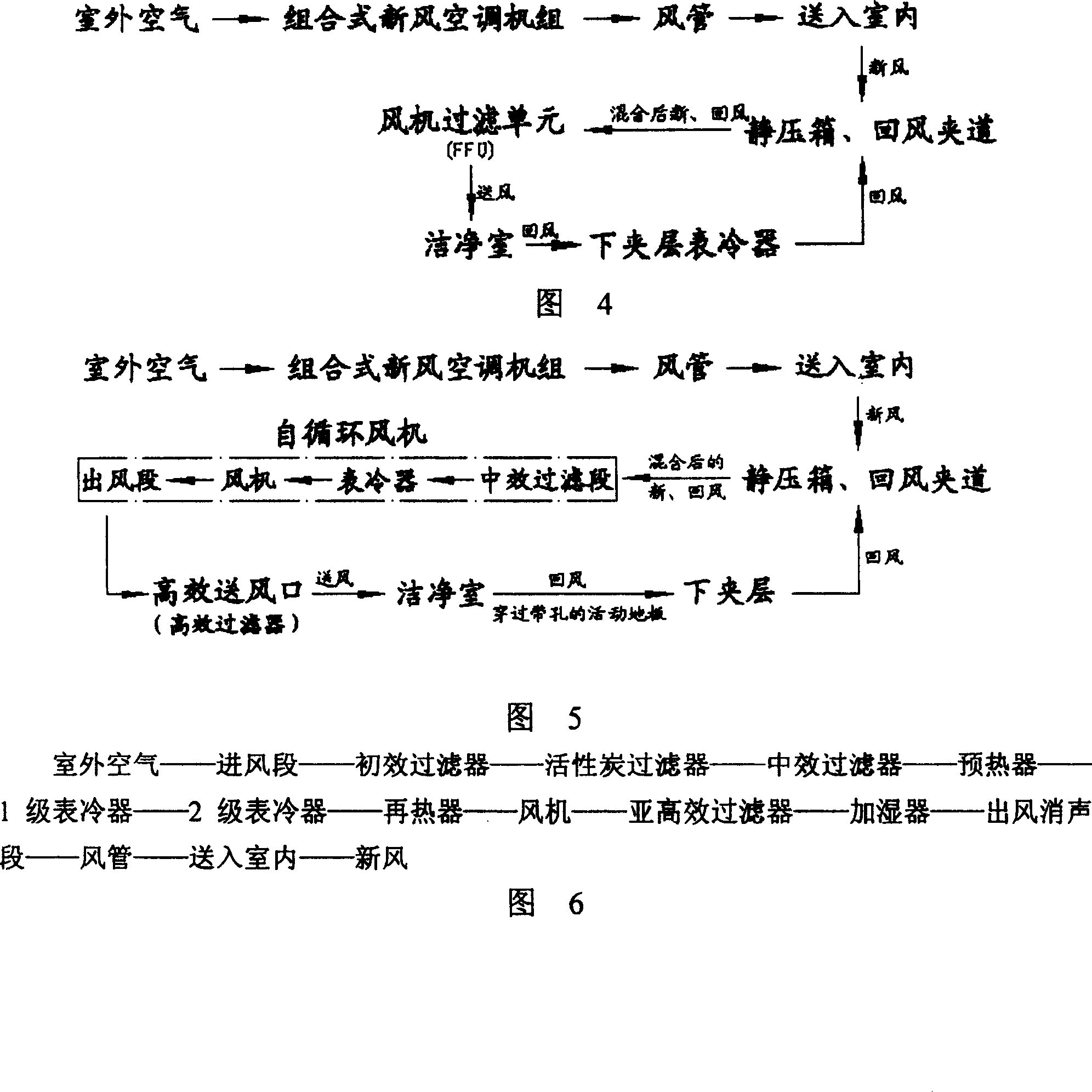
Flow pattern of air conditioning and purifying system in cleaning room
An air conditioning and purification system technology, applied in air conditioning systems, space heating and ventilation, household heating, etc., can solve problems affecting the service life of high-efficiency filters 1, air volume, wind pressure limitations, and small room for adjustment, etc., to achieve The effect of low noise, saving operating cost, and simplifying the sealing form
- Summary
- Abstract
- Description
- Claims
- Application Information
AI Technical Summary
Problems solved by technology
Method used
Image

Examples
Embodiment Construction
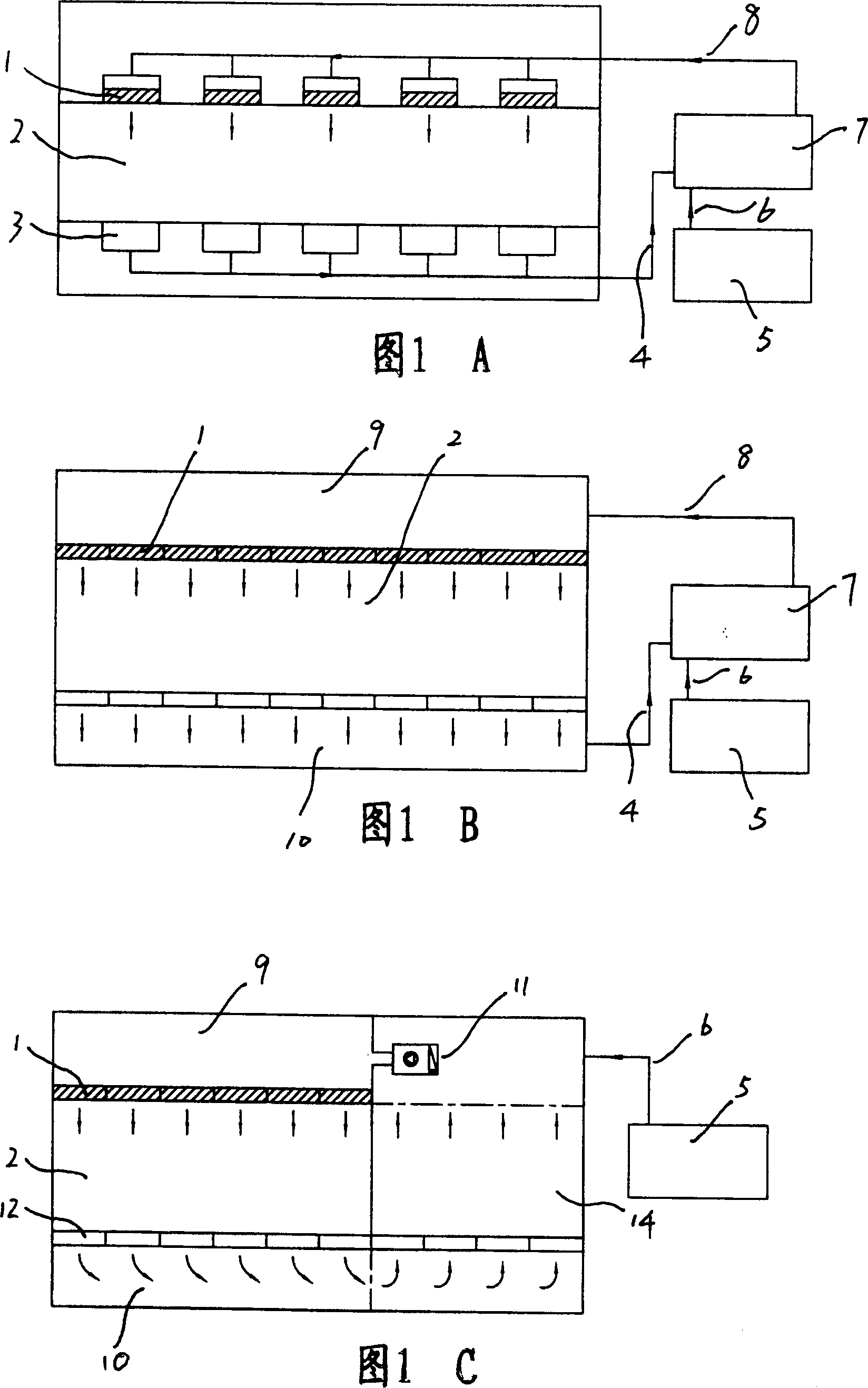
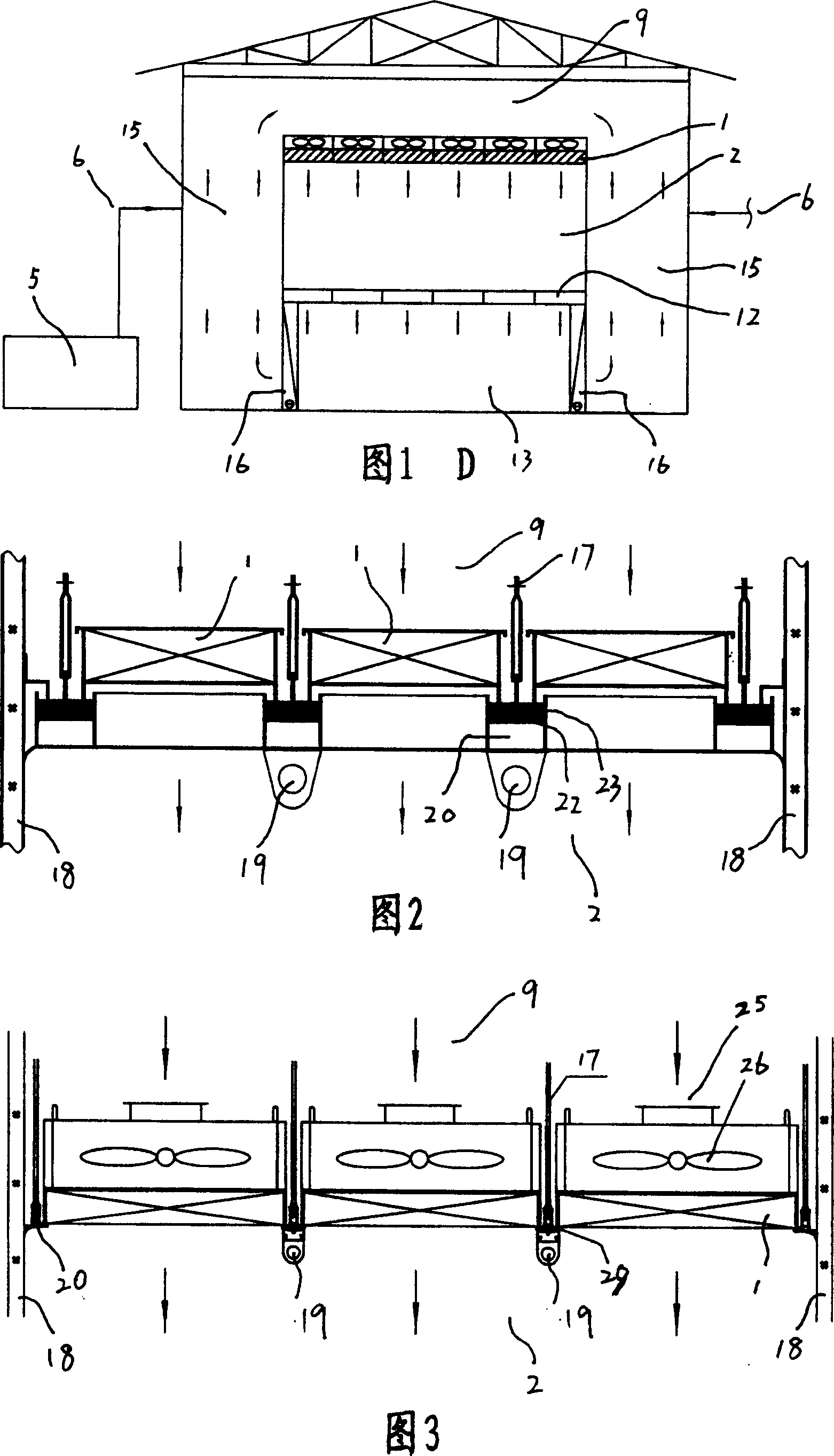
[0034] 1. High-efficiency filter, 2. Clean room, 3. Return air outlet, 4. Return air, 5. Fresh air air conditioning unit, 6. Fresh air, 7. Circulating fan, 8. Air inlet, 9. Static pressure box layer, 10. Lower mezzanine, 11. Self-circulating fan, 12. Raised floor with holes, 14. Equipment area or return air area, 15. Return air duct, 16. Surface cooler, 17. Suspension rod, 18. Wall plate, 19. Clean lighting, 20, keel frame, 22, liquid tank, 23, sealant, 25, tuyere, 26, fan, 27, air duct, 28, shell, 29, sealing gasket.
[0035]As shown in Figure 7: a perforated raised floor 12 is set between the clean room 2 and the lower mezzanine 10 below to separate it. The top of the clean room 2 is a plenum chamber layer 9, and between the clean room 2 and the plenum chamber layer 9 That is, a high-efficiency filter 1 is arranged on the top of the clean room 2 . Both sides of the clean room 2 are return air passages 15, and the fresh air 6 is sent into the return air passage 15 by the fre...
PUM
 Abstract
Description
Claims
Application Information