Gypsum pulp dewatering device and method for wetting smoke desulfurizing system

A wet flue gas desulfurization and dehydration device technology, applied in separation methods, chemical instruments and methods, dispersed particle separation, etc., to achieve the effects of solving water balance, reducing water consumption, and narrowing the impact of corrosion

Inactive Publication Date: 2007-08-15
孙克勤 +3
View PDF2 Cites 6 Cited by
  • Summary
  • Abstract
  • Description
  • Claims
  • Application Information

AI Technical Summary

Problems solved by technology

[0003] Technical problem: In order to overcome the problems existing in the existing gypsum dehydration, the present invention provides a gypsum slurry dehydration device and dehydration method in a wet flue gas desulfurization system

Method used


Image

  • Gypsum pulp dewatering device and method for wetting smoke desulfurizing system

Examples


Embodiment Construction

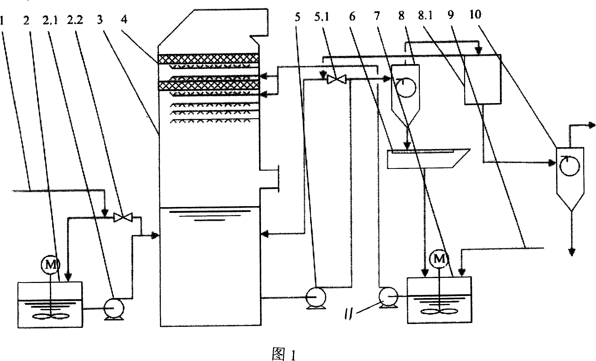
[0015] The gypsum slurry dehydration system and the limestone slurry conveying system of the present invention are composed of a limestone slurry tank 2, a limestone slurry pump 2.1, a limestone slurry return control valve 2.2, an absorption tower 3, a gypsum slurry discharge pump 5, and a gypsum slurry discharge pump return pipe control valve 5.1 , a vacuum belt conveyor 6, a filtrate tank 7, a gypsum cyclone 8, an overflow tank 8.1, and a waste water cyclone 10; wherein, the lower half of the limestone slurry tank 2 passes through the lower half of the limestone slurry pump 2.1 and the absorption tower 3 The pulping process water 1 is connected to the upper half of the limestone slurry tank 2 and communicates with the lower half of the absorption tower 3 through the limestone slurry backflow regulating valve 2.2; the upper part of the absorption tower 3 is provided with a demister 4 , the inlet of the gypsum slurry discharge pump 5 is connected to the lower half of the absorp...


PUM


Abstract

An apparatus for dewatering the gypsum slurry in wet fume-desulfurizing system is composed of lime stone slurry tank, lime stone slurry pump, the reflux regulating valve of lime stone slurry, absorption tower, gypsum slurry discharging pump, the reflux regulating valve of gypsum slurry, vacuum belt machine, filtrate tank, gypsum cyclone unit, overflow tank and waste water cyclone unit. Its dewatering process is also disclosed. Its advantages are high effect and low water consumption.

Description

technical field [0001] The invention relates to a gypsum dehydration and limestone slurry delivery system used in a wet flue gas desulfurization system (WFGD), belonging to the technical field of wet flue gas desulfurization equipment manufacturing. Background technique [0002] The currently known gypsum dehydration and limestone slurry delivery system in this field adopts the following process flow. After the gypsum slurry is discharged from the desulfurization absorption tower, it enters the gypsum cyclone. , part of the overflow from the gypsum cyclone goes to the waste water cyclone, and part of it returns to the absorption tower. This process has the following problems: First, the gypsum discharge varies with the processing load of the absorption tower, so a return pipe must be installed at the end of the gypsum discharge pipe to return the excess gypsum slurry to the absorption tower. In order to prevent scaling, the discharge pipe must ensure a certain flow rate, th...

Claims


Application Information

Patent Timeline
Patent Type & Authority Patents(China)
IPC IPC(8): B01D53/78B01D53/96
Inventor 孙克勤
Owner 孙克勤
Why Eureka
Try Eureka