Method for recording magnetic recording medium
A recording method, a magnetic recording technology, applied in the direction of magnetic recording, magnetic recording head, different recording carrier forms, etc., can solve the problems of lack of steepness, high cost, and expensive magnetization offset at the end of the track
- Summary
- Abstract
- Description
- Claims
- Application Information
AI Technical Summary
Problems solved by technology
Method used
Image

Examples
Embodiment 1
[0054] A recording method on a magnetic recording medium according to Embodiment 1 of the present invention will be described with reference to the drawings.
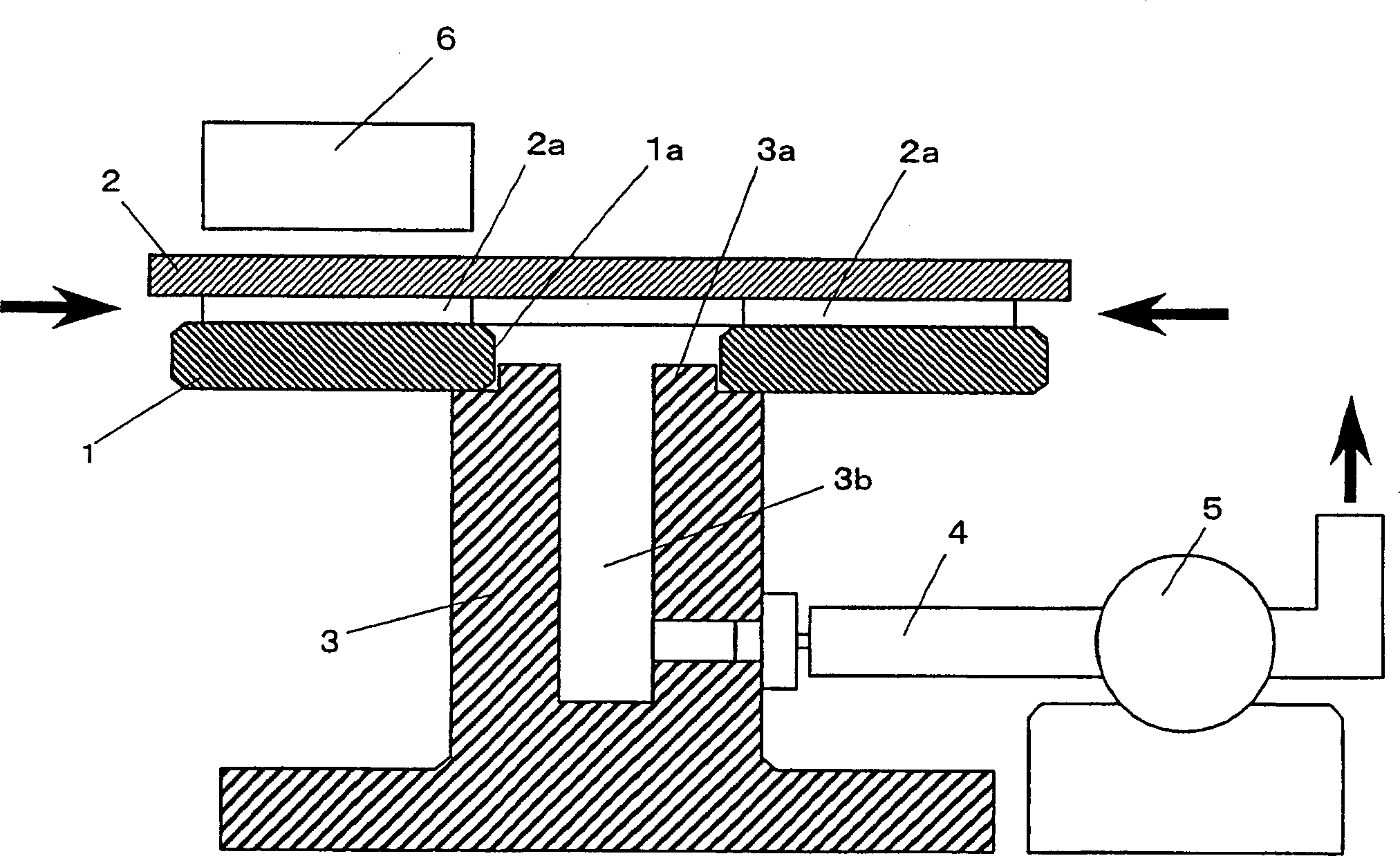
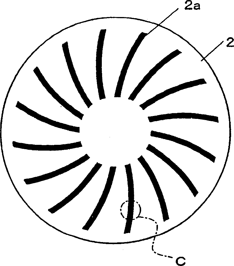
[0055] figure 1 A simple configuration of a recording apparatus for carrying out the recording method of this embodiment is shown. figure 1 Among them, 1 is a disk-shaped hard disk as a disk-shaped magnetic recording medium. In the hard disk 1, a ferromagnetic thin film made of cobalt or the like is formed by sputtering on the surface of an annular disc-shaped aluminum substrate having a central hole 1a. 2 is a disc-shaped master information carrier, which is overlapped and arranged to be in contact with the surface of a magnetic film made of a ferromagnetic thin film or the like of the hard disk 1 . The master information carrier 2 is larger in diameter than the hard disk, and a signal area 2a made of a ferromagnetic thin film is arranged on the surface of the side contacting the hard disk 1 . The ferromagnetic thin...
Embodiment 2
[0087] Figure 15 The magnetized head of Example 2 shown is the first example of the magnetized head used in the recording method of the present invention. Figure 15 Shows a section parallel to the circular magnetic circuit of the magnetic circuit of the magnetization head, that is, a section in the track length direction of an information signal, for example, a section in the circumferential direction of a disk-shaped magnetic recording medium. This magnetized head constitutes a ring-shaped magnetic circuit having a first core half body 21 having a yoke shape and a second core half body 22 having a yoke shape opposing to each other with a gap 23 . The outer peripheral shape of the section parallel to the annular magnetic circuit of this magnetic circuit is substantially formed into a polygon having a curved shape at least at the apex adjacent to the gap 23 portion. Specifically, at least the vertices adjacent to the gap 23, that is, the vertices 24A and 24B in the figure, a...
Embodiment 3
[0097] Figure 19 The magnetized head of Example 3 shown is the second example of the magnetized head used in the recording method of the present invention. Figure 19 Shows a cross section parallel to the circular magnetic circuit of the magnetic circuit, that is, a cross section in the track length direction of an information signal, for example, a cross section in the circumferential direction of a disk-shaped magnetic recording medium. This magnetized head is configured as a ring-shaped magnetic circuit in which a first core half body 31 having a yoke shape and a second core half body 32 having a yoke shape face each other with a gap 33 therebetween. The outer peripheral shape of the cross section parallel to the annular magnetic circuit of the magnetic circuit is formed substantially in a polygon whose inner angle at least at the apex adjacent to the gap portion is 100 degrees or more. that is, Figure 19 As shown, the outer peripheral shape of the cross-section paralle...
PUM
| Property | Measurement | Unit |
|---|---|---|
| Coercivity | aaaaa | aaaaa |
Abstract
Description
Claims
Application Information
 - R&D
- Intellectual Property
- Life Sciences
- Materials
- Tech Scout
- Unparalleled Data Quality
- Higher Quality Content
- 60% Fewer Hallucinations
Browse by: Latest US Patents, China's latest patents, Technical Efficacy Thesaurus, Application Domain, Technology Topic, Popular Technical Reports.
© 2025 PatSnap. All rights reserved.Legal|Privacy policy|Modern Slavery Act Transparency Statement|Sitemap|About US| Contact US: help@patsnap.com