
Magnetic toner

a technology of magnetic toner and binder resin, applied in the field of magnetic toner, can solve the problems of reducing the dispersion between a binder resin and an internal additive of a magnetic body, fluctuation or deterioration of anyone of various properties requested for magnetic toner, development properties and durability, etc., and achieves excellent fine-line reproducibility, increased process speed, and increased toner loading weight.

Active Publication Date: 2010-03-16
CANON KK
View PDF32 Cites 44 Cited by
  • Summary
  • Abstract
  • Description
  • Claims
  • Application Information

AI Technical Summary

Benefits of technology

The present invention provides a magnetic toner that solves problems such as image quality, developability, tailing, and photosensitive member flaw. The magnetic toner has a binder resin and a magnetic body with specific properties, such as magnetization and particle size. The magnetic toner also has good fixability and low toner consumption. Overall, the magnetic toner improves image quality and reproducibility, and solves issues in the printing process.

Problems solved by technology

However, when the particle size of toner is merely reduced, dispersibility between a binder resin and another internal additive of a magnetic body reduces, so toner performance is apt to be influenced by the reduction.
In particular, in the case of magnetic toner used for a one-component development mode in which a reduction in size of an apparatus is advantageous, the dispersed state of a magnetic body in the toner may cause a problem such as the fluctuation or deterioration of anyone of various properties requested for magnetic toner such as development property and durability.
On the other hand, when the amount of magnetic body particles on the toner particles is excessively large, charge is apt to leak, so a high charge amount is hardly obtained.
For example, fine-line reproducibility is apt to reduce, or image roughness is remarkable, so it becomes difficult to cope with a recent demand for high image quality.
When magnetic body particles are insufficiently dispersed into magnetic toner particles and a variation in magnetic properties of toner particles is excessively wide, napping is apt to be disturbed.
When the napping is disturbed (the napping is excessively long, excessively thick, or is nonuniform in size), for example, a problem in which the napping scatters to the periphery of an image or a problem in which fogging in which a non-image portion is developed with toner is apt to be remarkable occurs.
In addition, when napping is excessively long or excessively thick, a toner mounting height on a photosensitive member increases, so the tailing of a fixed image due to thermocompression fixing is apt to occur.
In addition, when the napping shape of magnetism remains even on transfer residual toner, a flaw tends to occur on the photosensitive member owing to rubbing with a cleaning blade.
At the same time, the progress of the selective development may further accelerate the above problems.
Meanwhile, when development conditions are set in such a manner that an image density is sufficiently high (for example, the amplitude of the alternating component of a developing bias is increased), particularly in the case where napping is disturbed, excessive toner is apt to be used for development, so the toner mounting amount of an image increases.
As a result, image quality is apt to deteriorate, fogging is apt to be remarkable, or a toner consumption is apt to increase.
However, merely adding the above metals has been still unable to reduce a toner consumption, so the particles are susceptible to improvement.
However, the method involves the emergence of a problem such as an increase in fogging in a development method using an alternating electric field particularly at a low temperature and a low humidity, so the method is not sufficient for the achievement of the stabilization of image quality or a reduction in consumption.
However, the magnetization of the toner is so low that the toner cannot be used for a one-component developer.
Therefore, the toner has been still unable to alleviate reductions in image quality and developability in long-term use particularly in a high-speed, large-capacity cartridge sufficiently, to reduce a toner consumption sufficiently, and to alleviate the tailing of a fixed image sufficiently, so the toner is susceptible to improvement.
However, napping may be disturbed after the performance of a long-term durability test.
However, when the particle size of toner is reduced for achieving high image quality, fogging is accelerated.

Method used


Image

  • Magnetic toner
  • Magnetic toner
  • Magnetic toner

Examples


production examples 3 to 5

of Magnetic Body

[0220]In each of Production Examples 3 and 4, each of magnetic bodies 3 and 4 was produced in the same manner as in Production Example 1 of Magnetic body except that: the temperature at which the oxidation reaction was performed and the time period for which the oxidation reaction was performed were changed; and the amount of the aqueous solution of sodium silicate was changed. In Production Example 5 (magnetic body 5), a magnetic body 5 was produced in the same manner as in Production Example 1 of Magnetic body except that: the temperature at which the oxidation reaction was performed and the time period for which the oxidation reaction was performed were changed; the amount of the aqueous solution of sodium silicate was changed; and the classifying step after the filtration and drying of the produced maternal magnetic body was omitted. Table 1 shows the physical properties of the magnetic bodies 3 to 5.

production example 6

of Magnetic Body

[0221]A maternal magnetic body F having an octahedral shape was produced in the same manner as in Production Example 1 of Magnetic body except that: the temperature at which the oxidation reaction was performed, the time period for which the oxidation reaction was performed, and the pH at which the oxidation reaction was performed were changed; and the classifying step after the filtration and drying of the produced magnetic body was omitted.

[0222]Next, the maternal magnetic body F was dispersed into water to prepare an aqueous suspension having a concentration of 100 g / l, and the temperature of the aqueous suspension was held at 60 to 80° C. An aqueous solution of sodium hydroxide or dilute sulfuric acid was added to adjust the pH of the aqueous suspension to 10 to 11. An aqueous solution of aluminum sulfate having a Al2O3 concentration of 100 g / l was added in an amount equivalent to 5.6 mass % in terms of Al2O3 / Fe3O4 to the aqueous suspension over about 1 hour whil...

production example 7

of Magnetic Body

[0225]A magnetic body having an octahedral shape and coated with Al2O3 was produced in the same manner as in Production Example 6 of Magnetic body except that: the temperature at which the oxidation reaction was performed and the time period for which the oxidation reaction was performed were changed; and the amount of the aqueous solution of aluminum sulfate was changed. After that, the magnetic body was subjected to a heat treatment at 175° C. for 30 minutes in the air. Thus, a magnetic body 7 was produced. Table 1 shows the physical properties of the magnetic body 7.


PUM


Abstract

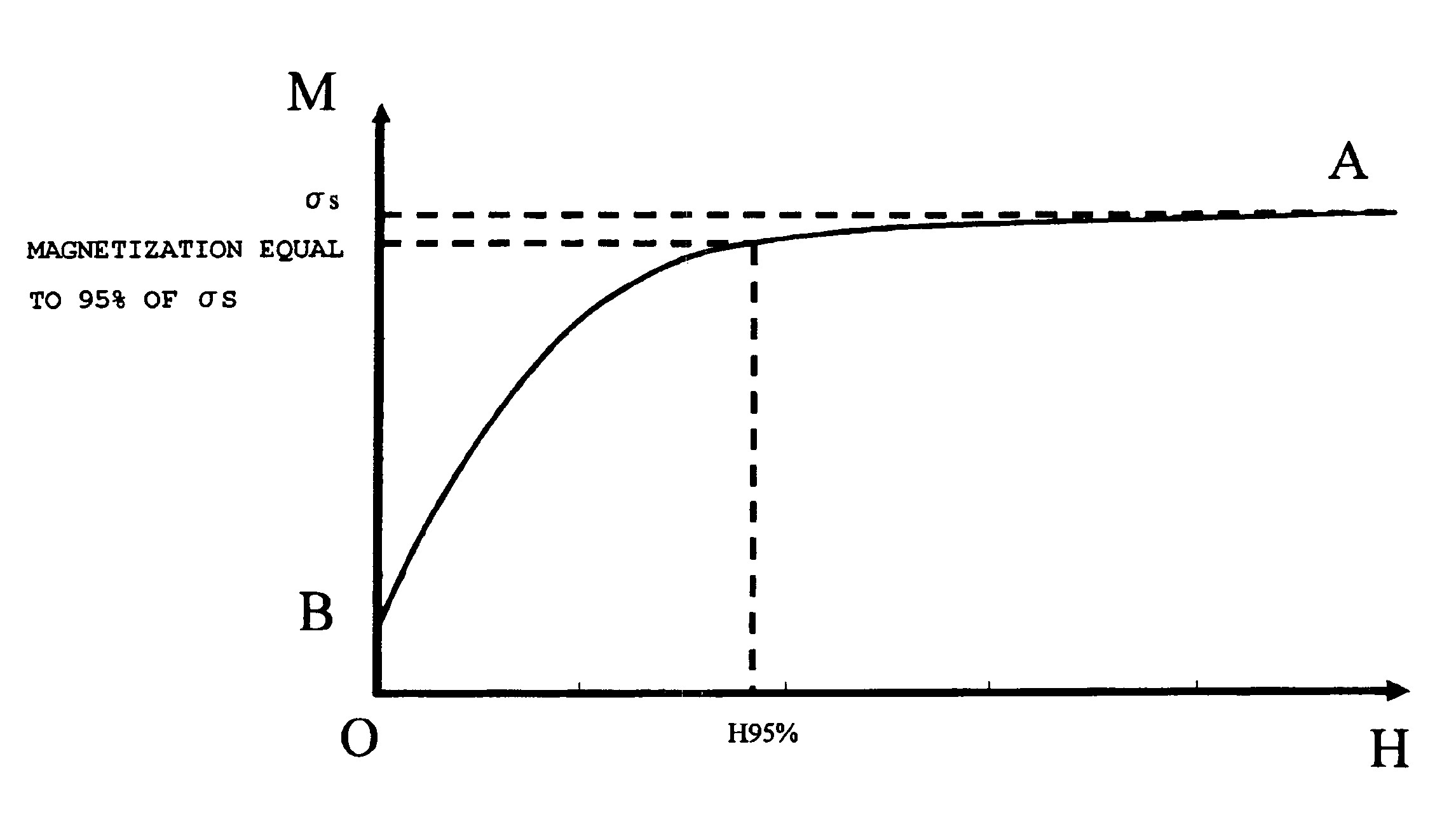
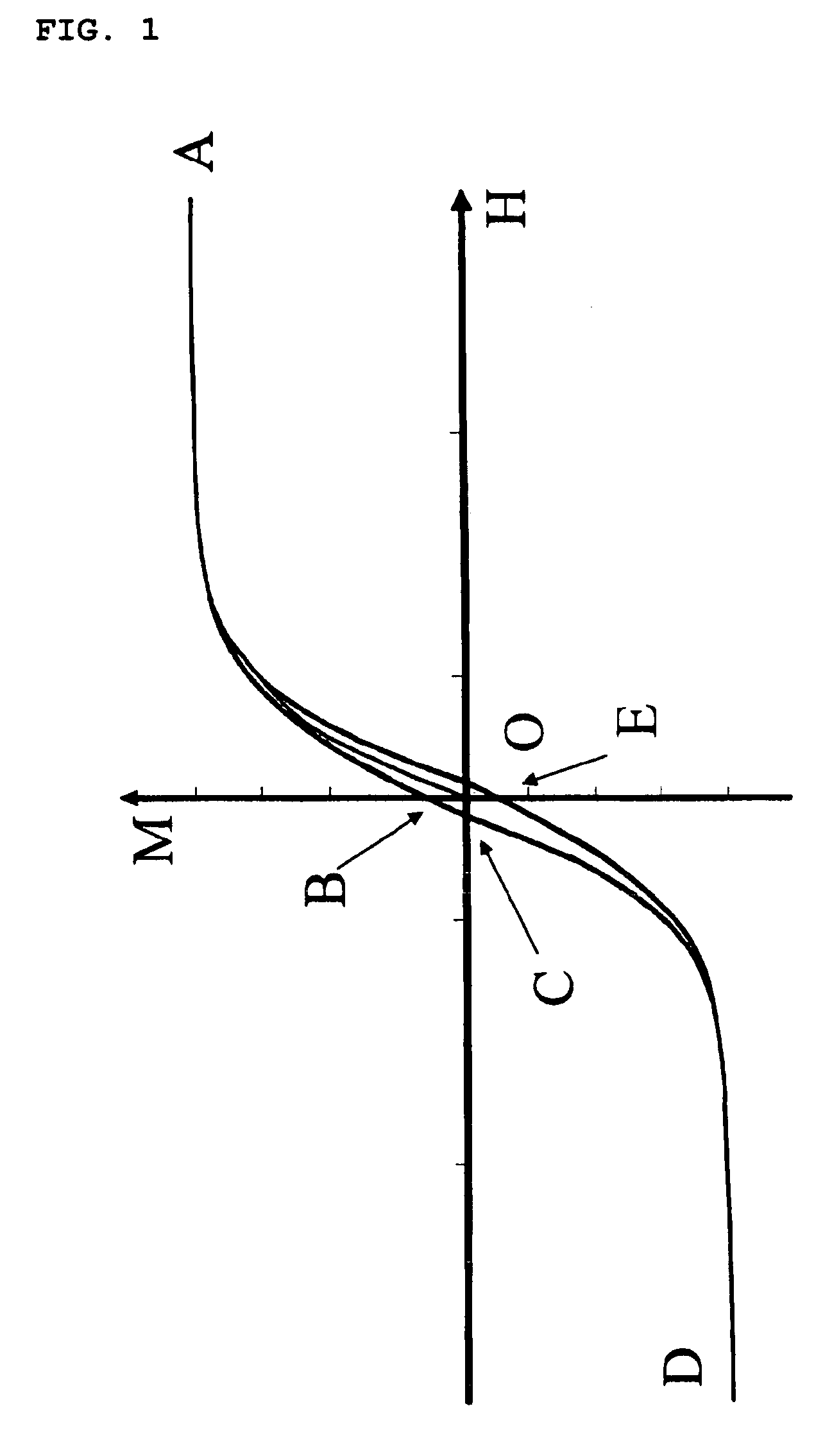
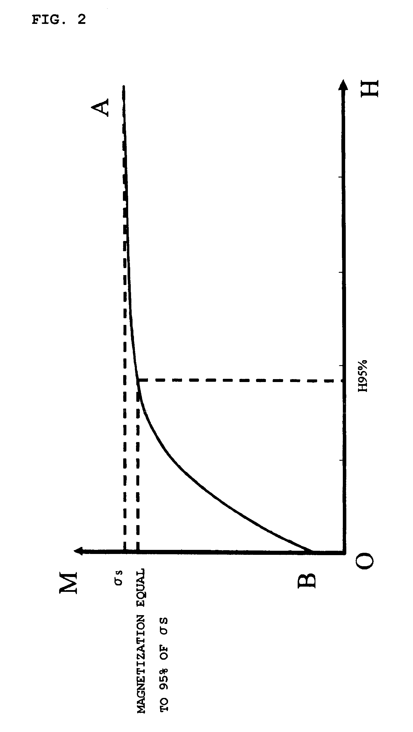
A magnetic toner including at least: a binder resin; and a magnetic body, in which, when magnetization at a magnetic field strength of 397.9 kA / m and a coercive force of the magnetic toner are denoted by σs (Am2 / kg) and Hc (kA / m), respectively, a magnetic field strength at which the magnetic toner shows a magnetization value equal to 95% of σs is denoted by H95% (kA / m), and a number average particle size of the magnetic body is denoted by d (μm), H95%, Hc, and d satisfy the following expressions.151<H95%<200  (1)7.1<Hc<12  (2)40<Hc / d<150  (3)

Description

BACKGROUND OF THE INVENTION[0001]1. Field of the Invention[0002]The present invention relates to a magnetic toner to be used for visualizing an electrostatic charge image in an image forming method for an electrophotograph or the like.[0003]2. Description of the Related Art[0004]In recent years, from a technical viewpoint, an image forming apparatus has been further requested to have a high speed and long-term high reliability in addition to high definition, high appearance quality, and high image quality. A reduction in particle size of toner and sharpening of a particle size distribution have been attempted to achieve a high-resolution and high-definition development mode. However, when the particle size of toner is merely reduced, dispersibility between a binder resin and another internal additive of a magnetic body reduces, so toner performance is apt to be influenced by the reduction. In particular, the influence is remarkable upon high-speed treatment or after long-term use.[0...

Claims


Application Information

Patent Timeline
Patent Type & Authority Patents(United States)
IPC IPC(8): G03G9/083
CPCG03G9/0819G03G9/0833G03G9/0834G03G9/0835G03G9/0836G03G9/0838G03G9/0839G03G9/08
Inventor HASEGAWA, YUSUKEOGAWA, YOSHIHIRONISHIYAMA, JUNKOOKAZAKI, MIHOKASUYA, TAKASHIGESANO, TOMOHISA
Owner CANON KK
Learn More