Mud level displaying alarm and well mud level monitoring method

A technology of liquid level display and alarm device, which is applied in the direction of buoy liquid level indicator, earthwork drilling, wellbore flushing, etc. It can solve the problems of not being able to deal with well kick and lost circulation in time, unintuitive image, and affecting normal post operations, etc. It is easy to distinguish the phenomenon of well kick and lost circulation, prevent well wall from collapsing and stuck pipe, and reduce labor intensity

Inactive Publication Date: 2002-05-08
HENGSHENG MECHANICS ZIZHONG COUNTY SICHUAN PROV
View PDF1 Cites 11 Cited by
  • Summary
  • Abstract
  • Description
  • Claims
  • Application Information

AI Technical Summary

Problems solved by technology

[0002] Existing drilling mud liquid level monitoring devices include multiple models such as mud pool liquid level monitoring and alarming devices and mud automatic pouring systems, such as a kind of "Automatic Filling Method for Tripping Drilling Mud" disclosed by the Chinese Patent Office with publication number CN1033858A One is to monitor the change of the mud level of the circulating tank group during the whole drilling process, and at the same time monitor the liquid flow of the overflow pipe, so as to take timely measures to deal with abnormal well kicks and lost circulation; A certain amount of mud is poured into the wellbore during drilling, lost circulation and stop drilling, to replenish the drop in wellbore liquid level caused by drilling tool pullout and lost circulation, so that the mud in the wellbore maintains a certain liquid column pressure and prevents the wellbore fluid from Column pressure and formation pressure are out of balance, and accidents such as well wall collapse and sticking, downhole oil and gas injection and other accidents occur; among them, the mud level monitoring and alarm device used in the mud pool liquid level alarm device and the mud liquid level alarm device used in the mud automatic injection system are composed of the box body, electrical circuit, etc. It consists of control panel, ten-pin socket, green mud level indicator, red kick indicator, yellow lost circulation indicator, and alarm horn. During the process of automatic mud injection, when the liquid flow in the overflow pipe is abnormal, the sound and light alarm will be given at the same time, but the mud level alarm device only uses red and yellow indicator lights to display and alarm, which is not intuitive, especially at the drilling site due to the large noise. When the operator cannot hear the alarm sound, the well kick and well leakage alarm cannot be judged only by the red and yellow indicator lights, so that the well kick and well leakage cannot be dealt with in time, leaving many potential safety hazards
[0003] At the same time, the method of using the original alarm device to monitor the wellbore mud level adopts a one-time and timely automatic control alarm, which has poor reliability. The normal phenomena such as the reduction of sand discharge fluid are mistakenly alarmed as well kicks and well leakages. False reports of well kicks or well leakages will also bring unnecessary mental pressure to operators in other positions, and even affect normal post operations. The quick control operation when drilling in oil and gas formations with well kick and lost circulation alarms will bury hidden dangers, and will also pose threats to drilling, equipment, and human safety due to monitoring errors or delayed alarms; in addition, this method does not automatically record alarm time, alarm Data, there is no evidence for post monitoring, measure decision-making, and accident analysis
Therefore, the traditional multi-post manual monitoring can only be used for alarming, leaving many potential safety hazards

Method used


Image

  • Mud level displaying alarm and well mud level monitoring method
  • Mud level displaying alarm and well mud level monitoring method
  • Mud level displaying alarm and well mud level monitoring method

Examples


Embodiment 1

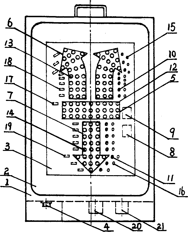
[0036] Example 1. During the drilling process, the mud level of the tank group is automatically displayed and alarmed, and the liquid level of the wellbore 41 is abnormally displayed:

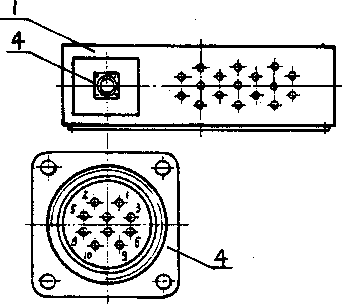
[0037] During the drilling process, the tripping / drilling button switch 42 is thrown at the "drilling" position, the controller 33 is connected to the 220V control power supply, and the power button 43 is pressed, the controller 33 passes the cable 44 and the mud level display alarm device 34 The No. 8 contact of the ten-core socket 4 is connected to the 24V voltage, the green mud level indicator light 5 is on, and the reset button 45 is pressed, and the mud level display alarm device 34 enters the mud tank 22, 23 groups of liquid levels to automatically display the alarm control state. The liquid level height signal detected by the floats 46 of the drilling mud tanks 22 and 23 is converted into the resistance signal of each potentiometer 50 by connecting the belt 47, the pulley 48 and the tran...

Embodiment 2

[0044] Example 2. Automatic display and alarm of the mud level of the tank group and the mud level of the wellbore 41 during the tripping process:

[0045] During the tripping process, the drilling pump 56 stops running, the kelly 61 is removed from the lower end screw and the faucet 60 is placed in the mouse hole, the drilling mud is not circulated, and the mud level display and alarm device is tanked in the same way as in Example 1. Group mud level automatic display alarm. Connect the 380V power supply, turn the tripping / drilling button switch 42 to the "tripping" position, and the mud level display alarm device 34 enters the state of automatic display and alarm control of the mud level of the tank group during the tripping process, and simultaneously enters the The wellbore mud level automatically displays the alarm control status.

[0046] Wellbore 41 mud level data is automatically displayed and printed:

[0047] During the drilling process, the drill pipe 62, the drill...


PUM


Abstract

The present invention relates to petroleum and natural gas well drilling. The mud level displaying alarm consists of control circuit board, ten pin socket, green mud level pilot lamp, red kick pilot lamp, yellow leakage pilot lamp, kick alarm and leakage alarm. It can monitor mud level during well drilling, send out acoustic and light warning of kick in red lamp and high frequency sound and leakage in yellow lamp and low frequency sound, and print automatically the mud level data. It is intuitive and reliable and makes it possible to ensure the safety of well, equipment and operator.

Description

Technical field: [0001] The invention relates to a device for displaying and alarming the mud level of the mud tank group and the wellbore during oil and gas drilling and tripping; method of liquid level monitoring. Background technique: [0002] Existing drilling mud liquid level monitoring devices include multiple models such as mud pool liquid level monitoring and alarming devices and mud automatic pouring systems, such as a kind of "Automatic Filling Method for Tripping Drilling Mud" disclosed by the Chinese Patent Office with publication number CN1033858A One is to monitor the change of the mud level of the circulating tank group during the whole drilling process, and at the same time monitor the liquid flow of the overflow pipe, so as to take timely measures to deal with abnormal well kicks and lost circulation; A certain amount of mud is poured into the wellbore during drilling, lost circulation and stop drilling, to replenish the drop in wellbore liquid level caused...

Claims


Application Information

Patent Timeline
Patent Type & Authority Applications(China)
IPC IPC(8): E21B21/08G01F23/30
Inventor 邓福泉易荣孙先国彭华龙
Owner HENGSHENG MECHANICS ZIZHONG COUNTY SICHUAN PROV
Why Eureka
Try Eureka