Self adapting equalizer and method
An adaptive equalization and equipment technology, applied in the direction of transmission control/equalization, radio/inductive link selection arrangement, baseband system components, etc., can solve problems such as response degradation and inability to obtain performance
- Summary
- Abstract
- Description
- Claims
- Application Information
AI Technical Summary
Problems solved by technology
Method used
Image
Examples
no. 1 example
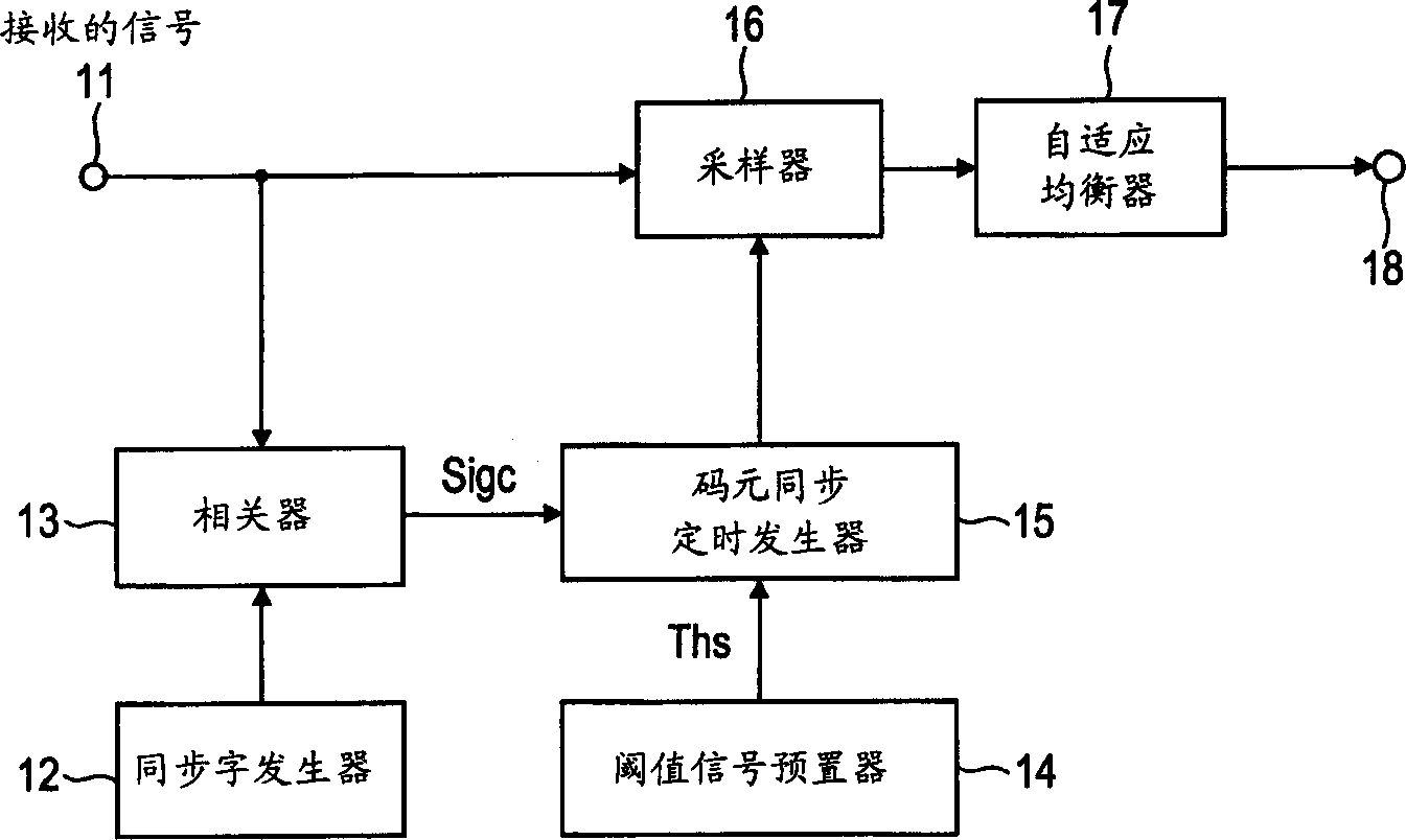
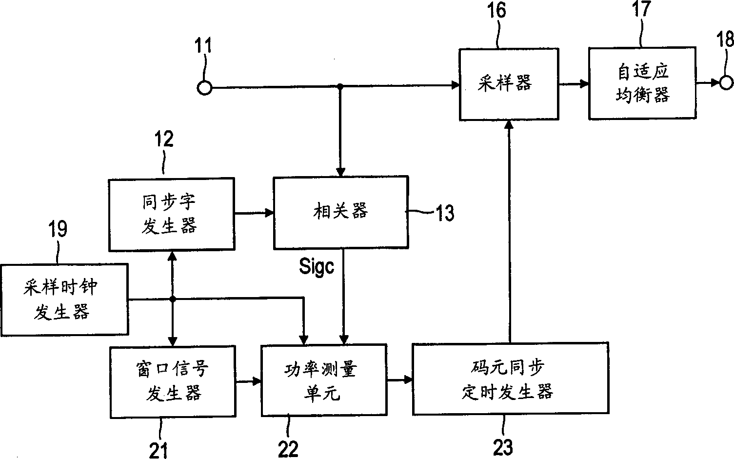
[0039] exist image 3 The configuration of the first embodiment of the present invention is shown in where using the figure 1 Like numerals are shown to indicate corresponding parts. The correlator 13 outputs a correlation value between the sync word signal generated by the sync word generator 12 and the received signal from the input terminal 11 . As used in conventional systems, the sync word signal used may comprise a symbol pattern, such as a PN code sequence, which, for example, provides high autocorrelation and low correlation with interference. Cross correlation to allow detection of the symbol timing of the desired signal while canceling the influence of interfering waves.
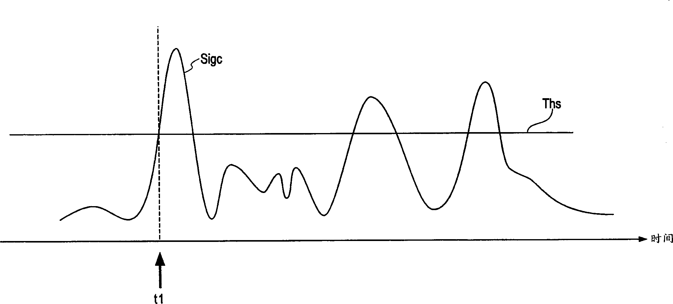
[0040]On the other hand, in this embodiment, a power measurement unit 22 is used to calculate the correlation output sum Sigc occurring within a given time range during which the time range is shifted in the time domain. For example, the window signal generator 21 supplies a window signal having...
no. 2 example
[0050] The difference between the second embodiment of the present invention and the first embodiment lies in the technique of measuring the relevant signal power in the power measurement unit 22 . In the replica generator 32 for the adaptive equalizer, the tapped input signal is provided over a given period of time, as shown in Fig. 7, so equalization is performed on the received signal sampled over that period of time. Therefore, by determining symbol synchronization timing in consideration of the time period of replica generator 32, path diversity gain can be obtained more efficiently. The tap period in an adaptive equalizer is usually equal to one symbol period. In this example, the power measurement unit 22 uses the following power measurement technique.
[0051] The correlation output signals within the windowed signal range are sampled over the symbol period, and the power sum of these sampled signals is calculated. This operation is repeated while shifting the time po...
no. 3 example
[0054] Figure 9 shows the configuration of the third embodiment of the present invention, in Figure 9 used in the corresponding image 3 The reference numerals used in refer to similar parts. In this embodiment, the adaptive equalizer provides temporal and spatial equalization combining adaptive antenna array processing and adaptive equalization processing.
[0055]The adaptive array antenna generates a beam pattern, which directs the beam with relatively high antenna gain to the direction of the desired signal that arranges its own signal according to the change of the signal condition in the adaptive mode, and will have obvious The null point of the reduced relative gain points in the direction of interfering signals carrying other user signals. Therefore, this technique effectively eliminates co-channel interference occurring between interfering signals using common frequencies (channels). The combination of adaptive array antenna and adaptive equalizer constitutes a ...
PUM
 Abstract
Description
Claims
Application Information
 - R&D
- Intellectual Property
- Life Sciences
- Materials
- Tech Scout
- Unparalleled Data Quality
- Higher Quality Content
- 60% Fewer Hallucinations
Browse by: Latest US Patents, China's latest patents, Technical Efficacy Thesaurus, Application Domain, Technology Topic, Popular Technical Reports.
© 2025 PatSnap. All rights reserved.Legal|Privacy policy|Modern Slavery Act Transparency Statement|Sitemap|About US| Contact US: help@patsnap.com


