Electronic music instrument
A technology of electronic musical instruments and musical sounds, applied in the direction of electro-acoustic musical instruments, instruments, etc., can solve problems such as gaps, achieve the effects of reducing manufacturing costs, low manufacturing costs, and maintaining life
- Summary
- Abstract
- Description
- Claims
- Application Information
AI Technical Summary
Problems solved by technology
Method used
Image

Examples
no. 1 example
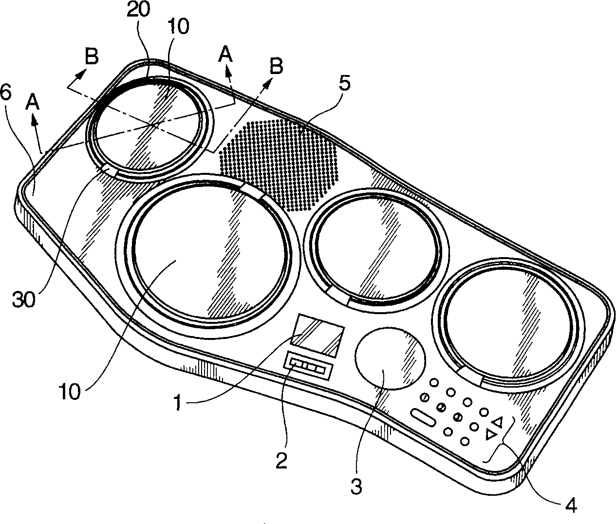
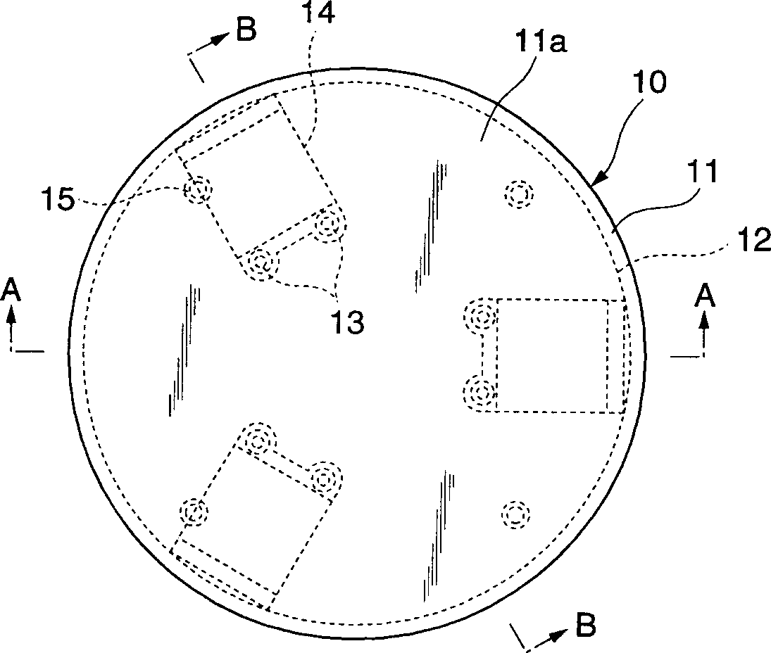
[0066] figure 1 is a schematic diagram of the appearance of the drum-type electronic musical instrument according to the first embodiment of the present invention.
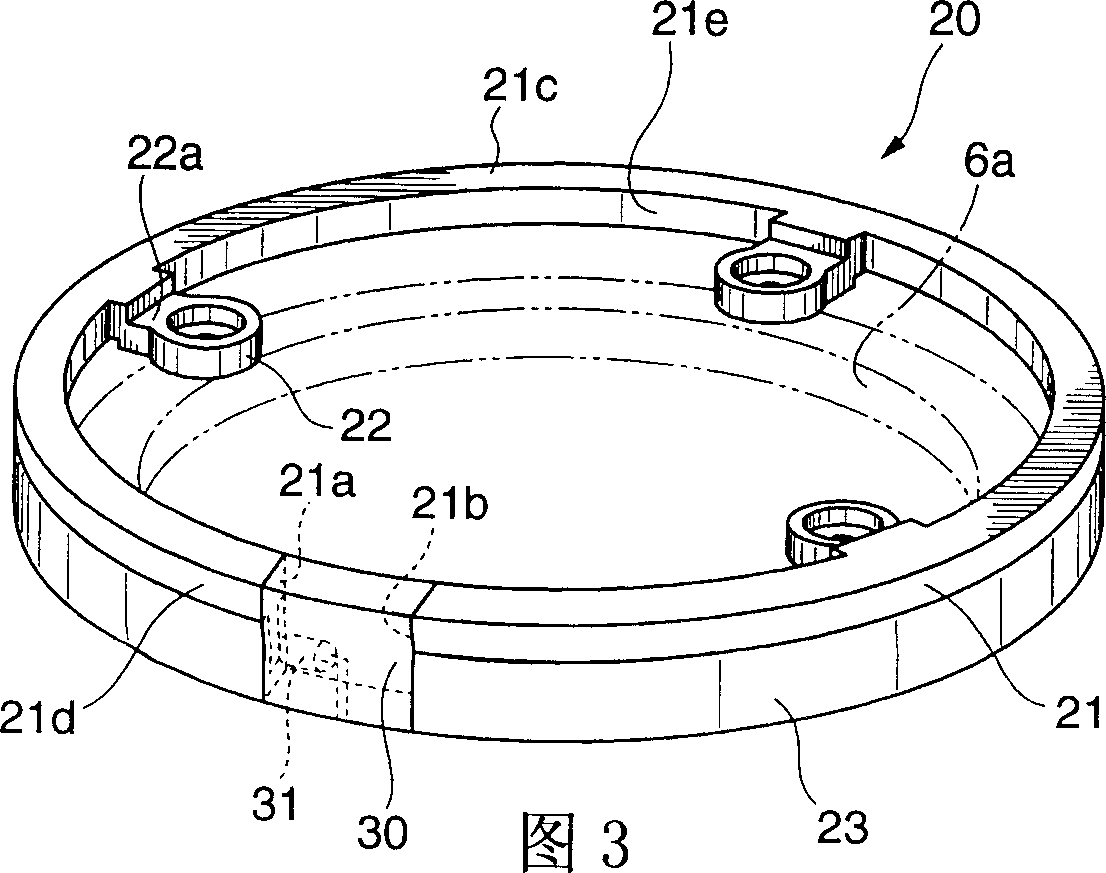
[0067] The electronic musical instrument according to the present embodiment includes a plurality of (four in the illustrated example) cushion members 10 provided on the upper casing 6 . Each upholstery member 10 has a ring-shaped light emitting unit 20 provided on its periphery. The light emitting unit 20 includes a light source 30 . As described below, in this embodiment, for example, by striking any of the cushion components 10, musical tones corresponding to the specified timbre (snare, bass drum, cymbal, etc.) of each cushion component are electronically produced, while , make the part of the light emitting unit 20 other than the light source 30 emit light. The plurality of components of the upholstery member 10 and the corresponding light emitting units 20 connected thereto are different in size, but subs...
no. 2 example
[0100] The difference between the second embodiment and the above-mentioned first embodiment is that the structure of the light emitting unit and the way of mounting the light emitting unit to the upper housing are different. The appearance of the electronic musical instrument according to the present embodiment, the structure of the cushion part 10, the sensor support part 40, the sensor part 41, the bridge part 14, and the elastic diaphragm part 42 are all the same as those of the first embodiment, so they will not be described in detail. illustrate.
[0101] Fig. 8 is a partial sectional view of the structure of the main part of the drum-type electronic musical instrument (hereinafter referred to as "electronic drum") according to the present embodiment, which is the same as that of the first embodiment. Figure 4 same edge figure 1 Partial sectional view of line A-A.
[0102] The light emitting unit 120 includes a light transmission body 121 , a reflector 123 and a light...
no. 3 example
[0113] Figure 9A is a partial cross-sectional view showing the configuration of a main part of an electronic musical instrument according to a third embodiment of the present invention. Figure 9B is a partial plan view of the fixed contact film. Figure 9A is the same as in the first embodiment Figure 4 same edge figure 1 Partial cross-sectional view of line A-A in .
[0114] In this embodiment, the vibration generated by the impact is not detected by the piezoelectric pressure sensor, but is detected by the contact switch. The structure of the light emitting unit 120, and the way in which the light emitting unit 120 is installed in the upper housing 506 are the same as in the second embodiment.
[0115] Such as Figure 9A As shown, the cushion component 310 includes a cushion skin component 311 and a backing plate 312 . The backing plate 312 is formed by forming an iron plate into a disc shape. The cushion skin member 311 is made of an elastic member such as rubber, a...
PUM
 Abstract
Description
Claims
Application Information
 - R&D
- Intellectual Property
- Life Sciences
- Materials
- Tech Scout
- Unparalleled Data Quality
- Higher Quality Content
- 60% Fewer Hallucinations
Browse by: Latest US Patents, China's latest patents, Technical Efficacy Thesaurus, Application Domain, Technology Topic, Popular Technical Reports.
© 2025 PatSnap. All rights reserved.Legal|Privacy policy|Modern Slavery Act Transparency Statement|Sitemap|About US| Contact US: help@patsnap.com