Numerical control method

A technology for controlling axes and time functions, applied in the field of numerical control, can solve the problems of position deviation, large error between commands, uneven acceleration integral feed, etc., and achieve the effect of reducing position deviation and reducing uneven feed.

Inactive Publication Date: 2002-07-10
YAMAZAKI MAZAK KK
View PDF0 Cites 8 Cited by
  • Summary
  • Abstract
  • Description
  • Claims
  • Application Information

AI Technical Summary

Problems solved by technology

Conventionally, the speed and acceleration commands in this control are made in the axis control section 51 based on the position command at the current sampling time, so sufficient control cannot be performed,

Method used


Image

  • Numerical control method
  • Numerical control method
  • Numerical control method

Examples


Embodiment Construction

[0028] specific implementation plan

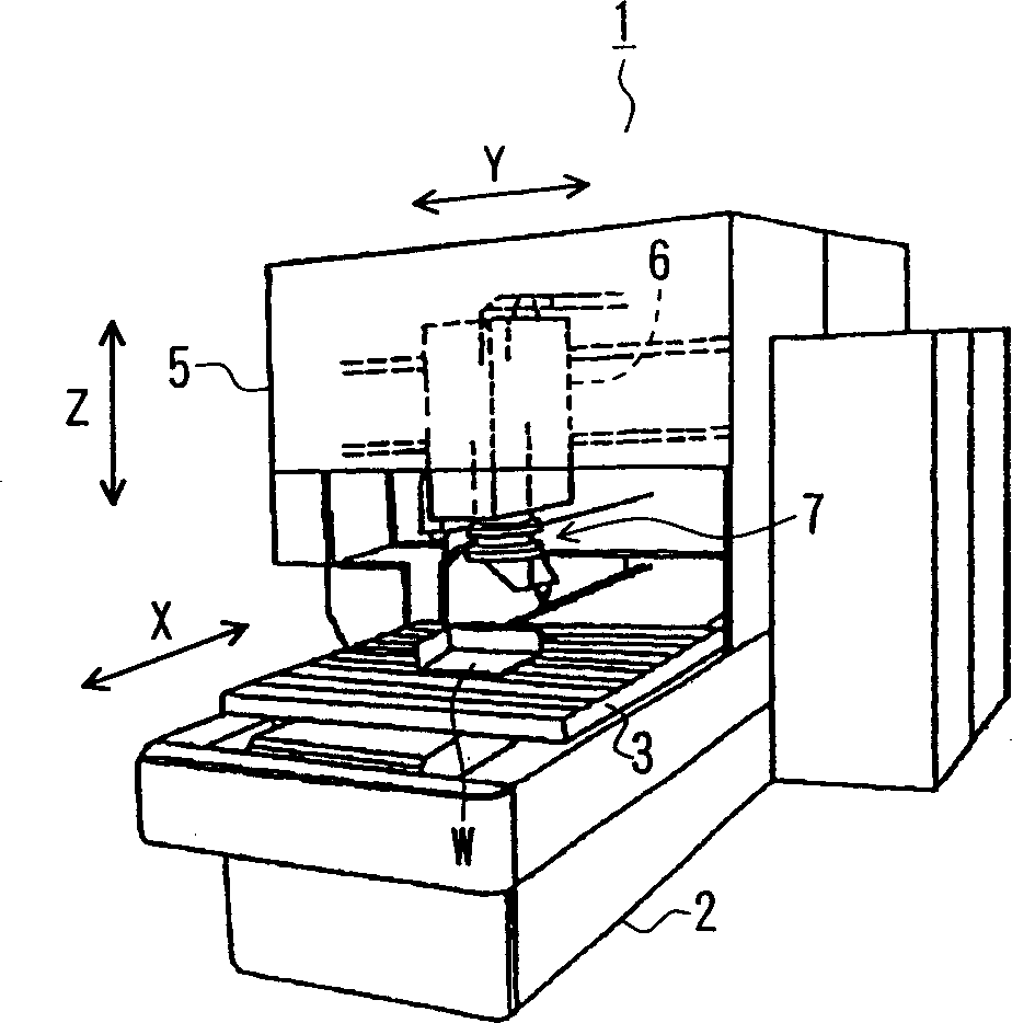
[0029] Fig. 3 is a diagram showing the appearance of the laser processing machine of the present embodiment. The laser processing machine 1 of this embodiment has a base 2 as shown in FIG. The workpiece W to be processed can be freely set on the table 3 . The base 2 is provided with a pillar 5, which straddles the above-mentioned platform 3, and a saddle 6 is arranged on the pillar 5, and it can be positioned in the horizontal Y-axis direction (the direction orthogonal to the above-mentioned X-axis direction) The drive moves freely.

[0030] A machine head assembly 7 is arranged on the above-mentioned saddle 6, and it can be driven and moved freely in the Z-axis direction as the up-down direction. On the head assembly 7, as shown in Figure 3(b), it is composed of the following parts: the first part 7a is located on the side of the saddle; the second part 7b is arranged to be parallel to the Z axis. 7a is centered on the axis CT1 of the...


PUM


Abstract

In a numerically controlled method of moving an object to be controlled along a predetermined locus, controlling control axes, the locus is made approximate to a spatial polynomial, a polynomial is converted into a polynomial as time function, the polynomial converted as time function is distributed to each control axis, control command in each control axis is produced on the basis of the polynomial distributed to each axis as time function, and the object to be controlled is moved along the locus, controlling each control axis on the basis of the control command. The velocity, the acceleration and the jerk of the object to be controlled can be easily obtained concerning each control axis in advance by differentiating the polynomial expressed by time function. The object to be controlled is controlled so as to move along the locus expressed by the polynomial, feeding irregularity or position shift is reduced and curved face machining at high accuracy is possible.

Description

technical field [0001] The present invention relates to a numerical control method capable of processing curved surfaces with high precision. Background technique [0002] Figure 7 It is a schematic diagram showing a conventional servo controller. Conventional servo control devices 60 used in laser processing machines and automatic switching CNC machine tools (machining centers), etc., when performing servo control of each axis with a three-dimensional spatial position command, based on the spatial position command and As for the speed command, the movement command for each control axis is generated in the axis command generation part 50, and these commands are necessary for realizing the position command and the speed command. [0003] The movement command for each axis thus generated is output to the corresponding axis control section, and in the axis control section, the motor is driven in accordance with the movement command. At this time, the position, speed and acce...

Claims


Application Information

Patent Timeline
IPC IPC(8): G05B19/4103G05B19/408G05B19/416
CPCG05B2219/41436G05B2219/34089G05B19/4086G05B2219/37323
Inventor 山崎恒彦大西公平宫川直臣井上利彦
Owner YAMAZAKI MAZAK KK
Why Eureka
Try Eureka